Difference between revisions of "D3. Interactions between rigid bodies"
| Line 280: | Line 280: | ||
</small> | </small> | ||
====✏️ EXAMPLE D3.4: constraint torsor associated with a continuous linear contact==== | |||
====✏️ | |||
--------- | --------- | ||
<small> | <small> | ||
[[ | [[File:ExD3-4-1-eng.png|left|175px|link=]] | ||
: | :The roller has a sliding contact with a horizontal ground S. The description of the multiple-point constraint as a superposition of single-point contacts leads to a set of infinite forces <math>\Ns_{\rightarrow \mathrm{J}}</math> at the contact points '''J''' in the direction orthogonal to the ground (direction 3). The resultant constraint force on the roller is therefore also in direction 3, and must be strictly positive since it is a unilateral constraint: | ||
<math>\int_{\mathrm{J} \in \text { | <math>\int_{\mathrm{J} \in \text { roller }} \mathrm{N}_{\rightarrow \mathrm{J}}=\mathrm{N}>0 .</math><br> | ||
The resultant constraint moment depends on the point on the roller at which it is calculated. At points '''P''' or '''Q''', the sign of resultant moment is given: | |||
<center> | <center> | ||
<math>\{\overline{\mathbf{M}}(\mathbf{P})\}=\left\{\int_{\text {J} \in \mathrm{ | <math>\{\overline{\mathbf{M}}(\mathbf{P})\}=\left\{\int_{\text {J} \in \mathrm{roller }} \overline{\mathbf{P J}} \times \overline{\mathbf{N}}_{\rightarrow \mathrm{J}}\right\}=\left\{\begin{array}{c} | ||
0 \\ | 0 \\ | ||
\mathbf{M}_2>0 \\ | \mathbf{M}_2>0 \\ | ||
0 | 0 | ||
\end{array}\right\},\{\overline{\mathbf{M}}(\mathbf{Q})\}=\left\{\int_{\text {J} \in \mathrm{ | \end{array}\right\},\{\overline{\mathbf{M}}(\mathbf{Q})\}=\left\{\int_{\text {J} \in \mathrm{roller }} \overline{\mathbf{QJ}} \times \overline{\mathbf{N}}_{\rightarrow \mathrm{J}}\right\}=\left\{\begin{array}{c} | ||
0 \\ | 0 \\ | ||
\mathbf{M}_2<0 \\ | \mathbf{M}_2<0 \\ | ||
| Line 307: | Line 303: | ||
\end{array}\right\} .</math> | \end{array}\right\} .</math> | ||
</center> | </center> | ||
[[ | [[File:ExD3-4-2-eng.png|center|700px|link=]] | ||
The description of the constraint through the torsor is very advantageous: it drastically reduces the number of constraint unknowns (we now have only two). If the torsor is characterized at '''P''' or '''Q''', the study of the limit condition for overturning is easy: <math>\mathrm{M}_2=0</math>. If it is characterized at any other point on the contact line, we must go to '''P''' or '''Q''' to investigate the overturning. | |||
===Analytical characterization of the constraint torsor between two rigid bodies S1 and S2=== | |||
The characterization of the constraint torsor between two rigid bodies can be done without going through the point-to-point description of the constraint: if the characterization point belongs to one of the two rigid bodies, it is enough to combine the orthogonality condition between force and velocity at each contact point with the rigid solid kinematics, and add all the equations that result from it ('''Figure D3.10'''). | |||
[[File:D3-10-eng.png|thumb|center|800px|link=]] | |||
[[File:D3-10-eng-bis.png|thumb|center|800px|link=]] | |||
[[ | |||
<center> | <center> | ||
<small>''' | <small>'''Figure D3.10''' Analytical characterization of a multiple-point contact between two rigid bodies.</small> | ||
</small> | |||
</center><br> | </center><br> | ||
Vectors <math>\overline{\mathbf{v}}_\mathrm{S2}(\Ps) \text{ and }\overline{\boldsymbol{\Omega}}_\mathrm{S2}^\mathrm{S1}</math> can be factored out. Finally: | |||
<math> \Biggl(\sum_\mathrm{J} \overline{\mathbf{F}}_{\rightarrow \mathrm{J}} \Biggl) \cdot \overline{\mathbf{v}}_\mathrm{S2}(\Ps) + \Biggr[ \sum_\mathrm{J} (\overline{\mathbf{PJ}} \times \mathbf{F}_{\rightarrow \mathrm{J}}) \Biggr] \cdot \overline{\boldsymbol{\Omega}}_\mathrm{S2}^\mathrm{S1} = 0 \Rightarrow \overline{\mathbf{F}}_{\mathrm{S2}\rightarrow \mathrm{S1}}\cdot \overline{\mathbf{v}}_\mathrm{S2}(\Ps) + \overline{\mathbf{M}}_{\mathrm{S2}\rightarrow \mathrm{S1}}(\Ps) \cdot \overline{\boldsymbol{\Omega}}_\mathrm{S2}^\mathrm{S1}=0 </math><br> | <math> \Biggl(\sum_\mathrm{J} \overline{\mathbf{F}}_{\rightarrow \mathrm{J}} \Biggl) \cdot \overline{\mathbf{v}}_\mathrm{S2}(\Ps) + \Biggr[ \sum_\mathrm{J} (\overline{\mathbf{PJ}} \times \mathbf{F}_{\rightarrow \mathrm{J}}) \Biggr] \cdot \overline{\boldsymbol{\Omega}}_\mathrm{S2}^\mathrm{S1} = 0 \Rightarrow \overline{\mathbf{F}}_{\mathrm{S2}\rightarrow \mathrm{S1}}\cdot \overline{\mathbf{v}}_\mathrm{S2}(\Ps) + \overline{\mathbf{M}}_{\mathrm{S2}\rightarrow \mathrm{S1}}(\Ps) \cdot \overline{\boldsymbol{\Omega}}_\mathrm{S2}^\mathrm{S1}=0 </math><br> | ||
This is the equation of the '''analytical characterization''' of the constraint torsor. It establishes the orthogonality between the constraint torsor <math>\bigl\{ \overline{\mathbf{F}}_{\mathrm{S2}\rightarrow \mathrm{S1}} \quad \overline{\mathbf{M}}_{\mathrm{S2}\rightarrow \mathrm{S1}}(\Ps)\bigl\}^\top</math> and the kinematic torsor <math>\bigl\{\overline{\mathbf{v}}_\mathrm{S2}(\Ps) \quad \overline{\boldsymbol{\Omega}}_\mathrm{S2}^\mathrm{S1} \bigl\}^\top</math> of S1 relative to S2: | |||
<math>\left\{\begin{array}{c} | |||
\overline{\mathbf{F}}_{\mathrm{S2}\rightarrow \mathrm{S1}}\\ | \overline{\mathbf{F}}_{\mathrm{S2}\rightarrow \mathrm{S1}}\\ | ||
\overline{\mathbf{M}}_{\mathrm{S2}\rightarrow \mathrm{S1}}(\Ps) | \overline{\mathbf{M}}_{\mathrm{S2}\rightarrow \mathrm{S1}}(\Ps) | ||
| Line 334: | Line 330: | ||
\end{array}\right\} =0.</math><br> | \end{array}\right\} =0.</math><br> | ||
This orthogonality does not imply orthogonality between force and velocity on the one hand, and between moment and angular velocity on the other. In principle, <math>\overline{\mathbf{F}}_{\mathrm{S2}\rightarrow \mathrm{S1}}\cdot \overline{\mathbf{v}}_\mathrm{S2}(\Ps) \neq 0 \text{, } \overline{\mathbf{M}}_{\mathrm{S2}\rightarrow \mathrm{S1}}(\Ps) \cdot \overline{\boldsymbol{\Omega}}_\mathrm{S2}^\mathrm{S1} \neq 0 </math>. | |||
When using the analytical characterization equation, it is initially necessary to consider that both the resulting force and moment have three non-zero components. As for the kinematic torsor, its non-zero components must be written as a function of the DoF of S1 relative to S2. | |||
Moreover, since the force and velocity of the point are multiplied scalarly on the one hand, and the moment and angular velocity on the other, different vector bases can be used for each of these scalar products, since the result does not depend on the basis: | |||
<math>\bigl\{\overline{\mathbf{F}}_{\mathrm{S2}\rightarrow \mathrm{S1}} \bigl\}_\mathrm{B} \cdot \bigl\{\overline{\mathbf{v}}_\mathrm{S2}(\Ps) \bigl\}_\mathrm{B} + \bigl\{\overline{\mathbf{M}}_{\mathrm{S2}\rightarrow \mathrm{S1}}(\Ps) \bigl\}_\mathrm{B'} \cdot \bigl\{\overline{\boldsymbol{\Omega}}_\mathrm{S2}^\mathrm{S1} \bigl\}_\mathrm{B'} </math> | <math>\bigl\{\overline{\mathbf{F}}_{\mathrm{S2}\rightarrow \mathrm{S1}} \bigl\}_\mathrm{B} \cdot \bigl\{\overline{\mathbf{v}}_\mathrm{S2}(\Ps) \bigl\}_\mathrm{B} + \bigl\{\overline{\mathbf{M}}_{\mathrm{S2}\rightarrow \mathrm{S1}}(\Ps) \bigl\}_\mathrm{B'} \cdot \bigl\{\overline{\boldsymbol{\Omega}}_\mathrm{S2}^\mathrm{S1} \bigl\}_\mathrm{B'} </math> | ||
====✏️ | ====✏️ EXAMPLE D3.5: analytical characterization of the constraint torsor associated with a linear contact==== | ||
--------- | --------- | ||
<small> | <small> | ||
[[ | [[File:ExD3-5-1-eng.png|thumb|left|165px|link=]] | ||
: | :The roller moves without sliding on the horizontal ground S. The analytical characterization of the torsor of the direct constraint of the ground on the roller, at point '''P''', is: | ||
:<math>\overline{\mathbf{F}}_{\mathrm{S}\rightarrow \mathrm{ | :<math>\overline{\mathbf{F}}_{\mathrm{S}\rightarrow \mathrm{roller}}\cdot \overline{\mathbf{v}}_\mathrm{S}(\Ps) + \overline{\mathbf{M}}_{\mathrm{S}\rightarrow \mathrm{roller}}(\Ps) \cdot \overline{\boldsymbol{\Omega}}_\mathrm{S}^\mathrm{roller}=0 </math><br> | ||
| Line 372: | Line 367: | ||
\end{array}\right\} =0</math><br> | \end{array}\right\} =0</math><br> | ||
All the components (but <math>\mathrm{M}_1</math>) of the constraint torsor can have any value, since they are multiplied by zero. However, since <math>\Omega_1</math> is not zero in principle, <math>\mathrm{M}_1</math> has to be zero for the orthogonality equation to be satisfied. Thus, the resulting constraint torsor is: | |||
<math>\bigl\{ \overline{\mathbf{F}}_{\mathrm{S}\rightarrow \mathrm{roller}} \quad \overline{\mathbf{M}}_{\mathrm{S}\rightarrow \mathrm{roller}}(\Ps)\bigl\}^\top = \bigl\{\mathrm{F}_1 \quad \mathrm{F}_2 \quad \mathrm{F}_3 \qquad 0 \quad \mathrm{M}_2 \quad \mathrm{M}_3 \bigl\}^\top . </math><br> | |||
<math>\bigl\{ \overline{\mathbf{F}}_{\mathrm{S}\rightarrow \mathrm{ | |||
As discussed in <span style="text-decoration: underline;">[[D3. Interactions between rigid bodies#✏️ EXAMPLE D3.4: constraint torsor associated with a continuous linear contact|'''example D3.4''']]</span>, has to be positive. A negative value would indicate overturning. | |||
The five non-zero components are independent, and it is true that the sum of the number of independent components of the torsor and that of DoF of the roller with respect to S is 6. | |||
The torsor of the same constraint at a different point can be obtained either by applying again the analytical characterization equation, or from the torsor at '''P''' (<span style="text-decoration: underline;">[[D3. Interactions between rigid bodies#D3.1 Torsor associated with a system of forces|'''section D3.1''']]</span>). For example, for point C these two methods lead to: | |||
* | * Analytical characterization: <math>\overline{\mathbf{F}}_{\mathrm{S}\rightarrow \mathrm{roller}}\cdot \overline{\mathbf{v}}_\mathrm{S}(\mathbf{C}) + \overline{\mathbf{M}}_{\mathrm{S}\rightarrow \mathrm{roller}}(\mathbf{C}) \cdot \overline{\boldsymbol{\Omega}}_\mathrm{S}^\mathrm{roller}=0 </math> | ||
| Line 402: | Line 396: | ||
0 \\ | 0 \\ | ||
0 | 0 | ||
\end{array}\right\} = 0 \quad \Rightarrow \quad \bigl\{ \overline{\mathbf{F}}_{\mathrm{S}\rightarrow \mathrm{ | \end{array}\right\} = 0 \quad \Rightarrow \quad \bigl\{ \overline{\mathbf{F}}_{\mathrm{S}\rightarrow \mathrm{roller}} \bigl\}= \left\{\begin{array}{c} | ||
\mathrm{F}_1\\ | \mathrm{F}_1\\ | ||
...\\ | ...\\ | ||
\mathrm{F}_3 | \mathrm{F}_3 | ||
\end{array}\right\} \quad \text{,} \quad \bigl\{ \overline{\mathbf{M}}_{\mathrm{S}\rightarrow \mathrm{ | \end{array}\right\} \quad \text{,} \quad \bigl\{ \overline{\mathbf{M}}_{\mathrm{S}\rightarrow \mathrm{roller}} (\mathbf{C}) \bigl\} =\left\{\begin{array}{c} | ||
...\\ | ...\\ | ||
\mathrm{M'}_2 \\ | \mathrm{M'}_2 \\ | ||
| Line 415: | Line 409: | ||
Finally: <math>\bigl\{ \overline{\mathbf{F}}_{\mathrm{S}\rightarrow \mathrm{roller}} \bigl\}=\left\{\begin{array}{c} | |||
\mathrm{F}_1\\ | \mathrm{F}_1\\ | ||
\mathrm{F}_2 \\ | \mathrm{F}_2 \\ | ||
\mathrm{F}_3 | \mathrm{F}_3 | ||
\end{array}\right\}\quad \text{,} \quad \bigl\{ \overline{\mathbf{M}}_{\mathrm{S}\rightarrow \mathrm{ | \end{array}\right\}\quad \text{,} \quad \bigl\{ \overline{\mathbf{M}}_{\mathrm{S}\rightarrow \mathrm{roller}} (\mathbf{C}) \bigl\} =\left\{\begin{array}{c} | ||
\mathrm{M'}_1\\ | \mathrm{M'}_1\\ | ||
\mathrm{M'}_2 \\ | \mathrm{M'}_2 \\ | ||
| Line 426: | Line 420: | ||
* | * From the constraint torsor at '''P''': <math>\overline{\mathbf{M}}_{\mathrm{S}\rightarrow \mathrm{roller}} (\mathbf{C})=\overline{\mathbf{M}}_{\mathrm{S}\rightarrow \mathrm{roller}} (\mathbf{P})+ \overline{\mathbf{CP}} \times \overline{\mathbf{F}}_{\mathrm{S}\rightarrow \mathrm{roller}} </math><br> | ||
:<math> \bigl\{ \overline{\mathbf{M}}_{\mathrm{S}\rightarrow \mathrm{ | :<math> \bigl\{ \overline{\mathbf{M}}_{\mathrm{S}\rightarrow \mathrm{roller}} (\mathbf{C}) \bigl\} =\left\{\begin{array}{c} | ||
0\\ | 0\\ | ||
\mathrm{M}_2 \\ | \mathrm{M}_2 \\ | ||
| Line 451: | Line 445: | ||
\end{array}\right\} </math><br> | \end{array}\right\} </math><br> | ||
: | :Finally: <math>\bigl\{ \overline{\mathbf{F}}_{\mathrm{S}\rightarrow \mathrm{roller}} \bigl\}=\left\{\begin{array}{c} | ||
\mathrm{F}_1\\ | \mathrm{F}_1\\ | ||
\mathrm{F}_2 \\ | \mathrm{F}_2 \\ | ||
\mathrm{F}_3 | \mathrm{F}_3 | ||
\end{array}\right\}\quad \text{,} \quad \bigl\{ \overline{\mathbf{M}}_{\mathrm{S}\rightarrow \mathrm{ | \end{array}\right\}\quad \text{,} \quad \bigl\{ \overline{\mathbf{M}}_{\mathrm{S}\rightarrow \mathrm{roller}} (\mathbf{C}) \bigl\} =\left\{\begin{array}{c} | ||
\mathrm{M'}_1\\ | \mathrm{M'}_1\\ | ||
\mathrm{M'}_2 \\ | \mathrm{M'}_2 \\ | ||
| Line 461: | Line 455: | ||
\end{array}\right\}</math>, amb <math>\mathrm{M'}_1=\rs\mathrm{F}_2</math><br> | \end{array}\right\}</math>, amb <math>\mathrm{M'}_1=\rs\mathrm{F}_2</math><br> | ||
The number of non-zero components of the torsor in '''C''' is 6, but the number of independent components is 5, since there is a dependency relationship between <math>\mathrm{M}_1'</math> and <math>\mathrm{F}_2</math>. Therefore, it is still true that the number of independent components of torsor plus that of DoF is 6. | |||
====✏️ EXAMPLE D3.6: analytical characterization of the constraint torsor associated with a nonsliding single-point contact==== | |||
====✏️ | |||
--------- | --------- | ||
[[ | [[File:ExD3-6-1-eng.png|thumb|left|200px|link=]] | ||
: | :The ball with radius r does not slide inside the spherical cavity. The analytical characterization of the torsor of the direct constraint of the cavity on the ball, at its center '''G''', is:<br> | ||
<math>\overline{\mathbf{F}}_{\mathrm{cav}\rightarrow \mathrm{ball}}\cdot \overline{\mathbf{v}}_\mathrm{cav}(\mathbf{G}) + \overline{\mathbf{M}}_{\mathrm{cav}\rightarrow \mathrm{ball}}(\mathbf{G}) \cdot \overline{\boldsymbol{\Omega}}_\mathrm{cav}^\mathrm{ball}=0 </math><br> | |||
<math>\overline{\mathbf{F}}_{\mathrm{cav}\rightarrow \mathrm{ | |||
| Line 489: | Line 481: | ||
\Omega_2\\ | \Omega_2\\ | ||
\Omega_3 | \Omega_3 | ||
\end{array}\right\} = 0 \quad \Rightarrow \quad \bigl\{ \overline{\mathbf{F}}_{\mathrm{cav}\rightarrow \mathrm{ | \end{array}\right\} = 0 \quad \Rightarrow \quad \bigl\{ \overline{\mathbf{F}}_{\mathrm{cav}\rightarrow \mathrm{ball}} \bigl\}= \left\{\begin{array}{c} | ||
...\\ | ...\\ | ||
\mathrm{F}_2\\ | \mathrm{F}_2\\ | ||
... | ... | ||
\end{array}\right\} \quad \text{,} \quad \bigl\{ \overline{\mathbf{M}}_{\mathrm{cav}\rightarrow \mathrm{ | \end{array}\right\} \quad \text{,} \quad \bigl\{ \overline{\mathbf{M}}_{\mathrm{cav}\rightarrow \mathrm{ball}} (\mathbf{G}) \bigl\} =\left\{\begin{array}{c} | ||
...\\ | ...\\ | ||
... \\ | ... \\ | ||
| Line 499: | Line 491: | ||
\end{array}\right\} </math> | \end{array}\right\} </math> | ||
Since there is no sliding at the contact point, the velocity components and are proportional to <math>\mathrm{v}_1</math> and <math>\mathrm{v}_3</math>, respectively: <math>\mathrm{v}_1=-\rs \Omega_3</math>, <math>\mathrm{v}_3=\rs \Omega_1</math> (the negative sign of the first equality indicates that a positive <math>\Omega_3</math> generates a negative <math>\mathrm{v}_1</math>). Substituting in the characterization equation and developing the scalar product (without including the component <math>\mathrm{F}_2</math>, because it is multiplied by zero): | |||
<math>(-\rs \mathrm{F}_1 + \mathrm{M}_3) \Omega_3 + (\rs \mathrm{F}_3 + \mathrm{M}_1) \Omega_1 + \mathrm{M}_2\Omega_2=0. </math><br> | <math>(-\rs \mathrm{F}_1 + \mathrm{M}_3) \Omega_3 + (\rs \mathrm{F}_3 + \mathrm{M}_1) \Omega_1 + \mathrm{M}_2\Omega_2=0. </math><br> | ||
Since the three rotations are independent, the coefficients that multiply them have to be zero for the equation to hold for any value of <math>\Omega_3</math> and of <math>\Omega_1</math>: <math>-\rs \mathrm{F}_1 + \mathrm{M}_3=0</math> ,<math>\rs \mathrm{F}_3 + \mathrm{M}_1</math> , <math>\mathrm{M}_2=0</math>. Finally: | |||
<math>\bigl\{ \overline{\mathbf{F}}_{\mathrm{cav}\rightarrow \mathrm{ball}} \quad \overline{\mathbf{M}}_{\mathrm{cav}\rightarrow \mathrm{ball}}(\mathbf{G})\bigl\}^\top = \bigl\{\mathrm{F}_1 \quad \mathrm{F}_2 \quad \mathrm{F}_3 \qquad \mathrm{M}_1 \quad 0 \quad \mathrm{M}_3 \bigl\}^\top</math>, amb <math>\mathrm{M}_3=\rs \mathrm{F}_1</math> i <math>\mathrm{M}_1=-\rs \mathrm{F}_3.</math><br> | |||
The torsor has five non-zero components, but only three are independent, and the sum of the number of independent components of the torsor and the DoF of the ball with respect to the cavity is 6. | |||
This torsor can also be obtained from the characterization at '''J''' (<span style="text-decoration: underline;">[[D3. Interactions between rigid bodies#D3.1 Torsor associated with a system of forces|'''section D3.1''']]</span>). Since it is a nonsliding contact point, there are three constraint force components and no moment at '''J''': | |||
<math>\bigl\{ \overline{\mathbf{F}}_{\mathrm{cav}\rightarrow \mathrm{ | <math>\bigl\{ \overline{\mathbf{F}}_{\mathrm{cav}\rightarrow \mathrm{ball}} \quad \overline{\mathbf{M}}_{\mathrm{cav}\rightarrow \mathrm{ball}}(\mathbf{J})\bigl\}^\top = \bigl\{\mathrm{F}_1 \quad \mathrm{F}_2 \quad \mathrm{F}_3 \qquad 0 \quad 0 \quad 0 \bigl\}^\top</math><br> | ||
<math>\overline{\mathbf{M}}_{\mathrm{cav}\rightarrow \mathrm{ | <math>\overline{\mathbf{M}}_{\mathrm{cav}\rightarrow \mathrm{ball}} (\mathbf{G})=\overline{\mathbf{M}}_{\mathrm{cav}\rightarrow \mathrm{ball}} (\mathbf{J})+ \overline{\mathbf{GJ}} \times \overline{\mathbf{F}}_{\mathrm{cav}\rightarrow \mathrm{ball}} = \overline{\mathbf{GJ}} \times \overline{\mathbf{F}}_{\mathrm{cav}\rightarrow \mathrm{ball}}</math><br> | ||
<math> \bigl\{ \overline{\mathbf{M}}_{\mathrm{cav}\rightarrow \mathrm{ | <math> \bigl\{ \overline{\mathbf{M}}_{\mathrm{cav}\rightarrow \mathrm{ball}} (\mathbf{G}) \bigl\} = \left\{\begin{array}{c} | ||
0\\ | 0\\ | ||
-\rs\\ | -\rs\\ | ||
| Line 545: | Line 530: | ||
----------- | ----------- | ||
As seen in the previous examples, the analytical characterization equation ensures that the sum of the number of independent components of the constraint torsor between two rigid bpdies and the number of relative DoF between them is always 6: | |||
<center><math>\boxed{\text{indep. torsor comps. + relative DoF = 6}}</math></center> | |||
===Straightforward characterization of the constraint torsor=== | |||
When we choose a characterization point '''P''' whose velocity, <math>\overline{\mathbf{v}}_{\mathrm{S1}}(\Ps)</math>, is independent from <math>\overline{\mathbf{\Omega}}_{\mathrm{S1}}^{\mathrm{S2}}</math>, and a vector basis such that the <math>\overline{\mathbf{v}}_{\mathrm{S1}}(\Ps)</math> components of are independent of each other and those of <math>\overline{\mathbf{\Omega}}_{\mathrm{S1}}^{\mathrm{S2}}</math> are also independent, '''the characterization is straightforward''': each zero component of the kinematic torsor corresponds to a non-zero component of the dynamic torsor, and each non-zero component of the kinematic torsor corresponds to a zero component of the dynamic torsor. | |||
====✏️ EXAMPLE D3.7: straightforward characterization of the constraint torsor associated with a continuous multiple-point contact==== | |||
--------- | |||
<small> | |||
[[File:ExD3-7-1-eng.png|thumb|left|200px|link=]] | |||
The conical millstone does not slide on the conical ground (E). The characterization of the direct constraint torque of the ground on the millstone at any of the contact points '''J''' can be straightforward, because <math>\vvec_\mathrm{E}(\mathbf{J})</math> independently of the angular velocity <math>\velang{millstone}{E}</math>. | |||
= | For the straightforward characterization to be possible, we must choose a vector basis for the constraint moment such that the <math>\velang{millstone}{E}</math> components of are independent. Since the <math>\velang{millstone}{E}</math> direction is univocally determined (the wheel has 1 DoF relative to the ground), any vector basis having an axis parallel to the millstone <span style="text-decoration: underline;">[[C4. Rigid body kinematics#C4.3 Geometry of the velocity distribution: Instantaneous Screw Axis (ISA)|'''ISA''']]</span> is suitable: | ||
Revision as of 10:25, 23 February 2025
[math]\displaystyle{ \newcommand{\uvec}{\overline{\textbf{u}}} \newcommand{\vvec}{\overline{\textbf{v}}} \newcommand{\evec}{\overline{\textbf{e}}} \newcommand{\Omegavec}{\overline{\mathbf{\Omega}}} \newcommand{\velang}[2]{\Omegavec^{\textrm{#1}}_{\textrm{#2}}} \newcommand{\Alfavec}{\overline{\mathbf{\alpha}}} \newcommand{\accang}[2]{\Alfavec^{\textrm{#1}}_{\textrm{#2}}} \newcommand{\ds}{\textrm{d}} \newcommand{\hs}{\textrm{h}} \newcommand{\Ns}{\textrm{N}} \newcommand{\Fs}{\textrm{F}} \newcommand{\ms}{\textrm{m}} \newcommand{\ts}{\textrm{t}} \newcommand{\us}{\textrm{u}} \newcommand{\vs}{\textrm{v}} \newcommand{\Rs}{\textrm{R}} \newcommand{\Ts}{\textrm{T}} \newcommand{\Ls}{\textrm{L}} \newcommand{\Bs}{\textrm{B}} \newcommand{\Ms}{\textrm{M}} \newcommand{\es}{\textrm{e}} \newcommand{\fs}{\textrm{f}} \newcommand{\is}{\textrm{i}} \newcommand{\js}{\textrm{j}} \newcommand{\rs}{\textrm{r}} \newcommand{\ss}{\textrm{s}} \newcommand{\Os}{\textbf{O}} \newcommand{\Gs}{\textbf{G}} \newcommand{\Cbf}{\textbf{C}} \newcommand{\Or}{\Os_\Rs} \newcommand{\Qs}{\textbf{Q}} \newcommand{\Cs}{\textbf{C}} \newcommand{\Ps}{\textbf{P}} \newcommand{\Ss}{\textbf{S}} \newcommand{\P}{\textrm{P}} \newcommand{\Q}{\textrm{Q}} \newcommand{\deg}{^\textsf{o}} \newcommand{\xs}{\textsf{x}} \newcommand{\ys}{\textsf{y}} \newcommand{\zs}{\textsf{z}} \newcommand{\dert}[2]{\left.\frac{\ds{#1}}{\ds\ts}\right]_{\textrm{#2}}} \newcommand{\ddert}[2]{\left.\frac{\ds^2{#1}}{\ds\ts^2}\right]_{\textrm{#2}}} \newcommand{\vec}[1]{\overline{#1}} \newcommand{\vecbf}[1]{\overline{\textbf{#1}}} \newcommand{\vecdot}[1]{\overline{\dot{#1}}} \newcommand{\OQvec}{\vec{\Os\Qs}} \newcommand{\QPvec}{\vec{\Qs\Ps}} \newcommand{\OPvec}{\vec{\Os\textbf{P}}} \newcommand{\OCvec}{\vec{\Os\Cs}} \newcommand{\OGvec}{\vec{\Os\Gs}} \newcommand{\abs}[1]{\left|{#1}\right|} \newcommand{\braq}[2]{\left\{{#1}\right\}_{\textrm{#2}}} \newcommand{\vector}[3]{ \begin{Bmatrix} {#1}\\ {#2}\\ {#3} \end{Bmatrix}} \newcommand{\vecdosd}[2]{ \begin{Bmatrix} {#1}\\ {#2} \end{Bmatrix}} \newcommand{\vel}[2]{\vvec_{\textrm{#2}} (\textbf{#1})} \newcommand{\acc}[2]{\vecbf{a}_{\textrm{#2}} (\textbf{#1})} \newcommand{\accs}[2]{\vecbf{a}_{\textrm{#2}}^{\textrm{s}} (\textbf{#1})} \newcommand{\accn}[2]{\vecbf{a}_{\textrm{#2}}^{\textrm{n}} (\textbf{#1})} \newcommand{\velo}[1]{\vvec_{\textrm{#1}}} \newcommand{\accso}[1]{\vecbf{a}_{\textrm{#1}}^{\textrm{s}}} \newcommand{\accno}[1]{\vecbf{a}_{\textrm{#1}}^{\textrm{n}}} \newcommand{\re}[2]{\Re_{\textrm{#2}}(\textbf{#1})} \newcommand{\psio}{\dot{\psi}_0} \newcommand{\Pll}{\textbf{P}_\textrm{lliure}} \newcommand{\agal}[1]{\vecbf{a}_{\textrm{Gal}} (#1)} \newcommand{\angal}[1]{\vecbf{a}_{\textrm{NGal}} (#1)} \newcommand{\vgal}[1]{\vecbf{v}_{\textrm{Gal}} (#1)} \newcommand{\fvec}[2]{\overline{\mathbf{F}}_{\textrm{#1}\rightarrow\textrm{#2}}} \newcommand{\mvec}[2]{\overline{\mathbf{M}}_{\textrm{#1}\rightarrow\textrm{#2}}} }[/math]
As seen in unit D2, interactions between pairs of particles P and Q are described by a single force with direction [math]\displaystyle{ \overline{\Ps \Qs} }[/math]. When the interaction is between pairs of rigid bodies (which can be considered as two sets of infinite particles), the particle-by-particle description would lead to a system of infinite forces. In this case, we must move on to a compact description of this system of forces that nevertheless retains the information necessary to study the dynamics of rigid bodies: the system of forces is replaced by a resultant torsor.
This unit introduces the concept of torsor associated with a system of forces, and then applies it to the various interactions between solids (at a distance, in contact, and through intermediate elements).
D3.1 Torsor associated with a system of forces
The reduction of a system of forces on a rigid body to a torsor is mandatory when the number of forces is very high (infinite). When it is a system of just a few forces, it is usually optional.
An effective mathematical operation to reduce the number of forces on a rigid body S is addition: however high the number of forces, the sum leads to a single resultant force. However, this drastic reduction implies a loss of essential information in many cases. As long as there is no interest in studying the deformation of objects (i.e., when only the dynamics of rigid bodies is studied), this is solved by adding a second vector to the compact description of the system: the resultant moment (or torque) about a point Q. The set of these two vectors (resultant force and resultant moment) is the torsor of the system of forces at point Q (Figure D3.1).

By way of an example, consider the case of a rigid bar initially at rest undergoing a system of forces with zero resultant force. Figure D3.2 shows three different situations corresponding to this situation: (a) free from forces, (b) forces parallel to the bar, (c) forces perpendicular to the bar. In the first two cases (a, b), the system of forces does not modify the state of rest. In the third case (c), the forces provoke a clockwise rotation of the bar. The resultant torsor at any point allows us to distinguish between (c) and (a, b).

The resultant force never depends on the point where the torsor is calculated. However, the resultant moment generally does depend on that point (Figure D3.3).
 |
[math]\displaystyle{
\hspace{1cm}\sum \overline{\Ms}(\Os) = (\Ls\Fs_\Ps+\Ls\Fs_\Qs) \otimes
}[/math]
[math]\displaystyle{ \hspace{1cm}\sum \overline{\Ms}(\Ps) = 2\Ls\Fs_\Qs \otimes }[/math] [math]\displaystyle{ \hspace{1cm}\sum \overline{\Ms}(\Qs) = 2\Ls\Fs_\Ps \otimes }[/math] [math]\displaystyle{ \hspace{1cm}\sum \overline{\Ms}(\Ss) = (3\Ls\Fs_\Ps-\Ls\Fs_\Qs) \otimes }[/math] |
The resulting torsor is represented at the point about which the resultant moment has been calculated (Figure D3.4).

The resultant moment about a point Q’ can be obtained from the torsor about a point Q:
[math]\displaystyle{ \overline{\mathbf{M}}_\mathrm{R}(\Qs ')=\overline{\mathbf{M}}_\mathrm{R}(\Qs) + \overline{\Qs '\Qs} \times \overline{\mathbf{F}}_\Rs }[/math]
💭 Proof ➕
- [math]\displaystyle{ \overline{\mathbf{M}}_\Rs(\Qs)=\sum \overline{\Qs \Ps_\is} \times \overline{\mathbf{F}}_\is }[/math]
- [math]\displaystyle{ \overline{\mathbf{M}}_\Rs(\Qs ')=\sum \overline{\Qs ' \Ps_\is} \times \overline{\mathbf{F}}_\is=\sum (\overline{\Qs ' \Qs}+\overline{\Qs \Ps_\is}) \times \overline{\mathbf{F}}_\is=\sum \overline{\Qs ' \Qs} \times \overline{\mathbf{F}}_\is + \sum \overline{\Qs \Ps_\is} \times \overline{\mathbf{F}}_\is=\overline{\Qs ' \Qs} \times (\sum \overline{\mathbf{F}}_\is) + \sum \overline{\Qs \Ps_\is} \times \overline{\mathbf{F}}_\is }[/math]
- [math]\displaystyle{ \overline{\mathbf{M}}_\Rs(\Qs ')=\overline{\Qs ' \Qs} \times \overline{\mathbf{F}}_\Rs+\overline{\mathbf{M}}_\Rs(\Qs) }[/math]
D3.2 Gravitational attraction
The calculation of the resultant gravitational torsor on a rigid body [math]\displaystyle{ \mathrm{S}_\mathrm{P} }[/math] due to a rígid body [math]\displaystyle{ \mathrm{S}_\mathrm{Q} }[/math] is not simple. The resultant gravitational force on a mass differential dm([math]\displaystyle{ \Ps }[/math]) of [math]\displaystyle{ \mathrm{S}_\mathrm{P} }[/math] ([math]\displaystyle{ \overline{\mathbf{F}}_{\mathrm{S}_{\mathrm{Q}} \rightarrow \Ps} }[/math]) is derived from the forces ([math]\displaystyle{ \overline{\mathbf{F}}_{\Qs \rightarrow \Ps} }[/math] ) that each mass differential exerts on P (Figure D3.5). The resultant torsor on [math]\displaystyle{ \mathrm{S}_\mathrm{P} }[/math] is obtained from all these forces [math]\displaystyle{ \overline{\mathbf{F}}_{\Qs \rightarrow \Ps} }[/math] on all mass differentials of [math]\displaystyle{ \mathrm{S}_\mathrm{P} }[/math].

When it comes to the Earth gravitational attraction ([math]\displaystyle{ \mathrm{S}_\mathrm{Q} = \mathrm{Earth} }[/math]) on a rigid body of small dimensions compared to those of the Earth and close to the Earth's surface, we usually apply the uniform field approximation: the forces [math]\displaystyle{ \overline{\mathbf{F}}_{\mathrm{S}_{\mathrm{Q}} \rightarrow \Ps} }[/math] are practically parallel to each other and their value is [math]\displaystyle{ \mathbf{F}_{\mathrm{S}_{\mathrm{Q}} \rightarrow \Ps} = \mathrm{gdm}(\Ps) }[/math], with g constant and equal to the gravitational field at the Earth's surface: [math]\displaystyle{ \mathrm{g}=\mathrm{G}_0 \frac{\mathrm{M}_\Ts}{\Rs_\Ts^2} }[/math] (where [math]\displaystyle{ \mathrm{G}_0 }[/math] is the universal gravitational constant, and [math]\displaystyle{ \mathrm{M}_\Ts }[/math] and [math]\displaystyle{ \Rs_\Ts }[/math] are the mass and radius of the Earth, respectively. In this case, it can be shown that there exists a point in [math]\displaystyle{ \mathrm{S}_\mathrm{P} }[/math] where the gravitational torsor is a resultant force [math]\displaystyle{ \overline{\mathbf{F}}_{\mathrm{S}_{\mathrm{T}} \rightarrow \mathrm{S}_{\mathrm{P}}} }[/math] with value mg (where m is the [math]\displaystyle{ \mathrm{S}_\mathrm{P} }[/math] mass) pointing towards the centre of the Earth, and a zero gravitational resultant moment. That point is the gravity centre of the rigid body, and will be represented by letter G (Figure D3.6).

D3.3 Interaction through linear and torsion springs and dampers
Linear springs and dampers
When a linear spring or a linear damper connects two points P and Q of two different rigid bodies, we have to guarantee that the connection is made in such a way that the force transmitted between the points has the direction of the element, and that no moment (or torque) is transmitted.
In some cases, this can be achieved by inserting the element between two lengths of inextensible thread (Figure D3.7a). Then, the force between points P and Q can only be an attraction (due to the unilateral nature of the thread action).
In other cases, it is necessary to use revolute joints (if it is a planar problem, Figure D3.7b) or spherical joints (if it is a 3D problem).

✏️ EXAMPLE D3.1: repulsion force of a linear spring and a linear damper with linear behaviour

- The spring, which has linear behaviour, acts between the support fixed to the ground and a vertical axis that is in contact with the bar. For [math]\displaystyle{ \theta = 0 }[/math], the system is in equilibrium, and the force exerted by the spring between its endpoints is [math]\displaystyle{ \mathrm{F}_0 }[/math].
- Without the spring, the bar, which is hinged to the support at point O, would fall (clockwise rotation). If there is equilibrium for [math]\displaystyle{ \theta = 0 }[/math], the spring must exert a repulsive force between its endpoints in that configuration. Therefore, the logical thing to do is to formulate the spring force for a general configuration as a repulsive force:
[math]\displaystyle{ \mathrm{F}_{\mathrm{rep}}^{\mathrm{spring}}= \mathrm{F}_0 - \mathrm{k}\Delta\rho=\mathrm{F}_0-\mathrm{k}[\rho(\theta) - \rho(\theta=0)] }[/math].
The length increase [math]\displaystyle{ \Delta \rho }[/math] of the spring from equilibrium configuration is proportional to the tangent of the angle: [math]\displaystyle{ \mathrm{tan}\theta=\Delta\rho/\mathrm{L} }[/math]. Therefore: [math]\displaystyle{ \mathrm{F}_{\mathrm{rep}}^{\mathrm{rping}}=\mathrm{F}_0-\mathrm{kL}\mathrm{tan}\theta }[/math].
The damper repulsion force can be obtained from the length increase through a time derivative:
[math]\displaystyle{ \rho=\mathrm{Ltan}\theta \Rightarrow \dot{\rho} = \frac{\mathrm{L}\dot{\theta}}{\mathrm{cos}^2\theta} \Rightarrow \mathrm{F}_{\mathrm{rep}}^{\mathrm{damper}}=\mathrm{c}\dot{\rho}=-\mathrm{c} \frac{\mathrm{L}\dot{\theta}}{\mathrm{cos}^2\theta} }[/math]
✏️ EXAMPLE D3.2: attraction force of a linear spring and a linear damper with linear behaviour

- The spring, with linear behaviour, has one endpoint fixed to the chassis of the vehicle, and the other one to an inextensible thread that wounds on a roller of radius r. That roller is fixed to the wheel of radius 2r, which does not slide on the ground. For [math]\displaystyle{ \xs = 0 }[/math], the spring is stretched and exerts a force [math]\displaystyle{ \mathrm{F}_0 }[/math] between its endpoints.

- The x coordinate describes the position of the chassis relative to the ground, and therefore also that of the centre of the wheel of radius 2r. Since the spring has one endpoint attached to a thread wounded on the roller, the displacement of this endpoint relative to the ground can be obtained through the integration of its speed.
- Given the velocities of the two spring endpoints, it is evident that its length is decreasing. The approaching speed between the endpoints is:
- [math]\displaystyle{ \mathrm{v}_{\mathrm{approaching}}(=-\dot{\rho})=\frac{3}{2}\dot{\xs}-\dot{\xs}=\frac{1}{2}\dot{\xs} }[/math]. Therefore, the spring length decrease from the [math]\displaystyle{ \xs = 0 }[/math] configuration is: [math]\displaystyle{ \frac{1}{2}\xs(=-\Delta \rho) }[/math].
- The spring attraction force (since [math]\displaystyle{ \mathrm{F}_0 }[/math] is an attraction force because the spring is stretched for [math]\displaystyle{ \xs = 0 }[/math]) is: [math]\displaystyle{ \mathrm{F}_{\mathrm{at}}^{\mathrm{spring}} + \mathrm{k}\Delta \rho = \mathrm{F}_0 - \frac{1}{2}\mathrm{k}\xs }[/math].
- The damper attraction force can be obtained from the approaching velocity calculated previously:
- [math]\displaystyle{ \mathrm{v}_{\mathrm{approaching}}(=-\dot{\rho})=\frac{1}{2}\dot{\xs} \Rightarrow \mathrm{F}_{\mathrm{at}}^{\mathrm{damper}}=\mathrm{c} \dot{\rho}=-\frac{1}{2} \mathrm{c} \dot{\xs} }[/math]
Torsion springs and dampers
Torsion springs and torsion dampers introduce moments (not forces) between the two rigid bodies they connect. As with linear elements, the connection to each rigid body must guarantee that no other moments but that of the spring or camper are transmitted. As with linear elements, there are several ways to achieve this.
When torsion springs and torsion dampers have a linear behaviour, the moment increment they introduce between the rigid bodies, when the relative orientation between them increases by an angle [math]\displaystyle{ \Delta \theta }[/math], is proportional to [math]\displaystyle{ \Delta \theta }[/math] and [math]\displaystyle{ \theta }[/math], respectively (Figure D3.8).

D3.4 Direct constraint interactions
Direct constraint interactions between two rigid bodies [math]\displaystyle{ \mathrm{S}_1 }[/math] and [math]\displaystyle{ \mathrm{S}_2 }[/math] occur when they are in contact, and they come from small local deformations of the rigid bodies in the contact zone. From a macroscopic point of view, this results in impenetrability and roughness of the rigid bodies. As mentioned in section D2.7, as this course deals with the dynamics of rigid objects, those deformations are not formulated, and therefore the associated forces are unknowns of the dynamic problem.
When the constraints involve rigid bodies (not particles), it is necessary to specify whether they are smooth or rough. A smooth surface cannot prevent an element from sliding on it while in contact. However, a rough surface can prevent this. This has a direct consequence on the constraint characterization.
As an introduction to the characterization of constraints between rigid bodies, it is useful to consider the simplest case of a single-point contact.
Let us consider two rigid bodies S1 and S2 with a single-point contact. The contact points are [math]\displaystyle{ \Ps_1 }[/math] and [math]\displaystyle{ \Ps_2 }[/math], respectively. The characterization of the constraint exerted by S2 on [math]\displaystyle{ \Ps_1 }[/math] (or exerted by S1 on [math]\displaystyle{ \Ps_2 }[/math]) is obtained as that of theparticle-surface constraint (Figure D3.9).

When the constraint between S1 and S2 is associated with a multiple-point contact, the orthogonality condition between the constraint force and the allowed velocity can be applied to each point where contact occurs (which implies accepting that the múltiple-point constraint can be obtained as a superposition of independent single-point contacts). Sometimes, this leads to a high number of constraint force components (even infinite, if contact occurs along a continuous linear section or a continuous surface section), and the force system must be reduced to a constraint torsor. In some cases, this reduction can be obtained very easily from the point-to-point constraint description.
Although it is possible to calculate the torsor of a system of forces at any point (section D3.1), when dealing with constraint torsors it is convenient that that point belongs to the rigid body undergoing that system of forces, because an important property is derived from it.
✏️ EXAMPLE D3.3: constraint torsor in a two-point contact

- The block has a two-point contact with a smooth floor, and has a planar motion.

- The description of the constraint as a superposition of two single-point contacts leads to two normal forces: if there were only contact at P, the constraint would introduce only a force at P orthogonal to the ground ([math]\displaystyle{ \Ns_\mathrm{P} }[/math]); if the contact were only at Q, it would introduce a force at Q orthogonal to the block ([math]\displaystyle{ \Ns_\mathrm{Q} }[/math]). The [math]\displaystyle{ \Ns_\mathrm{P} }[/math] and [math]\displaystyle{ \Ns_\mathrm{Q} }[/math] values are independent (knowing [math]\displaystyle{ \Ns_\mathrm{P} }[/math] does not imply knowing [math]\displaystyle{ \Ns_\mathrm{Q} }[/math]). The two-point contact, therefore, introduces two constraint unknowns.
Since there are only two forces, the reduction to a torsor is not necessary. On the other hand, this description is useful for studying the two limit conditions: [math]\displaystyle{ \Ns_\mathrm{P}=0 }[/math] indicates loss of contact at P (therefore, clockwise tipping), while [math]\displaystyle{ \Ns_\mathrm{Q}=0 }[/math] indicates loss of contact at Q (therefore, counterclockwise tipping).
In this case, the torsor associated with that system of forces does not reduce the number of unknowns, which is two. The resulting force has two independent components:
[math]\displaystyle{ \left\{\overline{\mathrm{F}}_{\mathrm{T} \rightarrow \text { block }}\right\}=\left\{\begin{array}{l} \mathrm{F}_1 \\ \mathrm{F}_2 \\ 0 \end{array}\right\} \text {, amb }\left\{\begin{array}{l} \mathrm{F}_1=-\mathrm{N}_{\mathrm{Q}} \sin \theta \\ \mathrm{F}_2=\mathrm{N}_{\mathrm{p}}+\mathrm{N}_{\mathrm{Q}} \cos \theta \end{array}\right. \text {. } }[/math]
The resulting moment depends on the point of the block where the torsor is characterized, and when it is not zero, it can be written in terms of the force components.

Moving from the point-to-point description to the torsor has no advantage in this case: it does not reduce the number of constraint unknowns, and it makes the study of boundary conditions more difficult.
✏️ EXAMPLE D3.4: constraint torsor associated with a continuous linear contact

- The roller has a sliding contact with a horizontal ground S. The description of the multiple-point constraint as a superposition of single-point contacts leads to a set of infinite forces [math]\displaystyle{ \Ns_{\rightarrow \mathrm{J}} }[/math] at the contact points J in the direction orthogonal to the ground (direction 3). The resultant constraint force on the roller is therefore also in direction 3, and must be strictly positive since it is a unilateral constraint:
[math]\displaystyle{ \int_{\mathrm{J} \in \text { roller }} \mathrm{N}_{\rightarrow \mathrm{J}}=\mathrm{N}\gt 0 . }[/math]
The resultant constraint moment depends on the point on the roller at which it is calculated. At points P or Q, the sign of resultant moment is given:
[math]\displaystyle{ \{\overline{\mathbf{M}}(\mathbf{P})\}=\left\{\int_{\text {J} \in \mathrm{roller }} \overline{\mathbf{P J}} \times \overline{\mathbf{N}}_{\rightarrow \mathrm{J}}\right\}=\left\{\begin{array}{c} 0 \\ \mathbf{M}_2\gt 0 \\ 0 \end{array}\right\},\{\overline{\mathbf{M}}(\mathbf{Q})\}=\left\{\int_{\text {J} \in \mathrm{roller }} \overline{\mathbf{QJ}} \times \overline{\mathbf{N}}_{\rightarrow \mathrm{J}}\right\}=\left\{\begin{array}{c} 0 \\ \mathbf{M}_2\lt 0 \\ 0 \end{array}\right\} . }[/math]

The description of the constraint through the torsor is very advantageous: it drastically reduces the number of constraint unknowns (we now have only two). If the torsor is characterized at P or Q, the study of the limit condition for overturning is easy: [math]\displaystyle{ \mathrm{M}_2=0 }[/math]. If it is characterized at any other point on the contact line, we must go to P or Q to investigate the overturning.
Analytical characterization of the constraint torsor between two rigid bodies S1 and S2
The characterization of the constraint torsor between two rigid bodies can be done without going through the point-to-point description of the constraint: if the characterization point belongs to one of the two rigid bodies, it is enough to combine the orthogonality condition between force and velocity at each contact point with the rigid solid kinematics, and add all the equations that result from it (Figure D3.10).
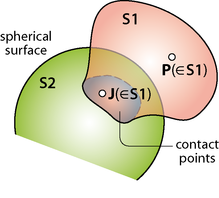

Figure D3.10 Analytical characterization of a multiple-point contact between two rigid bodies.
Vectors [math]\displaystyle{ \overline{\mathbf{v}}_\mathrm{S2}(\Ps) \text{ and }\overline{\boldsymbol{\Omega}}_\mathrm{S2}^\mathrm{S1} }[/math] can be factored out. Finally:
[math]\displaystyle{ \Biggl(\sum_\mathrm{J} \overline{\mathbf{F}}_{\rightarrow \mathrm{J}} \Biggl) \cdot \overline{\mathbf{v}}_\mathrm{S2}(\Ps) + \Biggr[ \sum_\mathrm{J} (\overline{\mathbf{PJ}} \times \mathbf{F}_{\rightarrow \mathrm{J}}) \Biggr] \cdot \overline{\boldsymbol{\Omega}}_\mathrm{S2}^\mathrm{S1} = 0 \Rightarrow \overline{\mathbf{F}}_{\mathrm{S2}\rightarrow \mathrm{S1}}\cdot \overline{\mathbf{v}}_\mathrm{S2}(\Ps) + \overline{\mathbf{M}}_{\mathrm{S2}\rightarrow \mathrm{S1}}(\Ps) \cdot \overline{\boldsymbol{\Omega}}_\mathrm{S2}^\mathrm{S1}=0 }[/math]
This is the equation of the analytical characterization of the constraint torsor. It establishes the orthogonality between the constraint torsor [math]\displaystyle{ \bigl\{ \overline{\mathbf{F}}_{\mathrm{S2}\rightarrow \mathrm{S1}} \quad \overline{\mathbf{M}}_{\mathrm{S2}\rightarrow \mathrm{S1}}(\Ps)\bigl\}^\top }[/math] and the kinematic torsor [math]\displaystyle{ \bigl\{\overline{\mathbf{v}}_\mathrm{S2}(\Ps) \quad \overline{\boldsymbol{\Omega}}_\mathrm{S2}^\mathrm{S1} \bigl\}^\top }[/math] of S1 relative to S2:
[math]\displaystyle{ \left\{\begin{array}{c}
\overline{\mathbf{F}}_{\mathrm{S2}\rightarrow \mathrm{S1}}\\
\overline{\mathbf{M}}_{\mathrm{S2}\rightarrow \mathrm{S1}}(\Ps)
\end{array}\right\} \cdot \left\{\begin{array}{c}
\overline{\mathbf{v}}_\mathrm{S2}(\Ps)\\
\overline{\boldsymbol{\Omega}}_\mathrm{S2}^\mathrm{S1}
\end{array}\right\} =0. }[/math]
This orthogonality does not imply orthogonality between force and velocity on the one hand, and between moment and angular velocity on the other. In principle, [math]\displaystyle{ \overline{\mathbf{F}}_{\mathrm{S2}\rightarrow \mathrm{S1}}\cdot \overline{\mathbf{v}}_\mathrm{S2}(\Ps) \neq 0 \text{, } \overline{\mathbf{M}}_{\mathrm{S2}\rightarrow \mathrm{S1}}(\Ps) \cdot \overline{\boldsymbol{\Omega}}_\mathrm{S2}^\mathrm{S1} \neq 0 }[/math].
When using the analytical characterization equation, it is initially necessary to consider that both the resulting force and moment have three non-zero components. As for the kinematic torsor, its non-zero components must be written as a function of the DoF of S1 relative to S2.
Moreover, since the force and velocity of the point are multiplied scalarly on the one hand, and the moment and angular velocity on the other, different vector bases can be used for each of these scalar products, since the result does not depend on the basis:
[math]\displaystyle{ \bigl\{\overline{\mathbf{F}}_{\mathrm{S2}\rightarrow \mathrm{S1}} \bigl\}_\mathrm{B} \cdot \bigl\{\overline{\mathbf{v}}_\mathrm{S2}(\Ps) \bigl\}_\mathrm{B} + \bigl\{\overline{\mathbf{M}}_{\mathrm{S2}\rightarrow \mathrm{S1}}(\Ps) \bigl\}_\mathrm{B'} \cdot \bigl\{\overline{\boldsymbol{\Omega}}_\mathrm{S2}^\mathrm{S1} \bigl\}_\mathrm{B'} }[/math]
✏️ EXAMPLE D3.5: analytical characterization of the constraint torsor associated with a linear contact

- The roller moves without sliding on the horizontal ground S. The analytical characterization of the torsor of the direct constraint of the ground on the roller, at point P, is:
- [math]\displaystyle{ \overline{\mathbf{F}}_{\mathrm{S}\rightarrow \mathrm{roller}}\cdot \overline{\mathbf{v}}_\mathrm{S}(\Ps) + \overline{\mathbf{M}}_{\mathrm{S}\rightarrow \mathrm{roller}}(\Ps) \cdot \overline{\boldsymbol{\Omega}}_\mathrm{S}^\mathrm{roller}=0 }[/math]
[math]\displaystyle{ \left\{\begin{array}{c}
\mathrm{F}_1\\
\mathrm{F}_2 \\
\mathrm{F}_3
\end{array}\right\}
\cdot \left\{\begin{array}{c}
0\\
0\\
0
\end{array}\right\} + \left\{\begin{array}{c}
\mathrm{M}_1\\
\mathrm{M}_2 \\
\mathrm{M}_3
\end{array}\right\} \cdot \left\{\begin{array}{c}
\Omega_1\\
0 \\
0
\end{array}\right\} =0 }[/math]
All the components (but [math]\displaystyle{ \mathrm{M}_1 }[/math]) of the constraint torsor can have any value, since they are multiplied by zero. However, since [math]\displaystyle{ \Omega_1 }[/math] is not zero in principle, [math]\displaystyle{ \mathrm{M}_1 }[/math] has to be zero for the orthogonality equation to be satisfied. Thus, the resulting constraint torsor is:
[math]\displaystyle{ \bigl\{ \overline{\mathbf{F}}_{\mathrm{S}\rightarrow \mathrm{roller}} \quad \overline{\mathbf{M}}_{\mathrm{S}\rightarrow \mathrm{roller}}(\Ps)\bigl\}^\top = \bigl\{\mathrm{F}_1 \quad \mathrm{F}_2 \quad \mathrm{F}_3 \qquad 0 \quad \mathrm{M}_2 \quad \mathrm{M}_3 \bigl\}^\top . }[/math]
As discussed in example D3.4, has to be positive. A negative value would indicate overturning.
The five non-zero components are independent, and it is true that the sum of the number of independent components of the torsor and that of DoF of the roller with respect to S is 6.
The torsor of the same constraint at a different point can be obtained either by applying again the analytical characterization equation, or from the torsor at P (section D3.1). For example, for point C these two methods lead to:
- Analytical characterization: [math]\displaystyle{ \overline{\mathbf{F}}_{\mathrm{S}\rightarrow \mathrm{roller}}\cdot \overline{\mathbf{v}}_\mathrm{S}(\mathbf{C}) + \overline{\mathbf{M}}_{\mathrm{S}\rightarrow \mathrm{roller}}(\mathbf{C}) \cdot \overline{\boldsymbol{\Omega}}_\mathrm{S}^\mathrm{roller}=0 }[/math]
- [math]\displaystyle{ \left\{\begin{array}{c} \mathrm{F}_1\\ \mathrm{F}_2 \\ \mathrm{F}_3 \end{array}\right\} \cdot \left\{\begin{array}{c} 0\\ \mathrm{v}_2 = - \rs \Omega_1\\ 0 \end{array}\right\} + \left\{\begin{array}{c} \mathrm{M'}_1\\ \mathrm{M'}_2 \\ \mathrm{M'}_3 \end{array}\right\} \cdot \left\{\begin{array}{c} \Omega_1\\ 0 \\ 0 \end{array}\right\} = 0 \quad \Rightarrow \quad \bigl\{ \overline{\mathbf{F}}_{\mathrm{S}\rightarrow \mathrm{roller}} \bigl\}= \left\{\begin{array}{c} \mathrm{F}_1\\ ...\\ \mathrm{F}_3 \end{array}\right\} \quad \text{,} \quad \bigl\{ \overline{\mathbf{M}}_{\mathrm{S}\rightarrow \mathrm{roller}} (\mathbf{C}) \bigl\} =\left\{\begin{array}{c} ...\\ \mathrm{M'}_2 \\ \mathrm{M'}_3 \end{array}\right\} }[/math]
- [math]\displaystyle{ (-\rs \mathrm{F}_2 + \mathrm{M'}_1)\Omega_1 =0 \quad \Rightarrow \quad -\rs\mathrm{F}_2 + \mathrm{M'}_1=0 }[/math]
Finally: [math]\displaystyle{ \bigl\{ \overline{\mathbf{F}}_{\mathrm{S}\rightarrow \mathrm{roller}} \bigl\}=\left\{\begin{array}{c}
\mathrm{F}_1\\
\mathrm{F}_2 \\
\mathrm{F}_3
\end{array}\right\}\quad \text{,} \quad \bigl\{ \overline{\mathbf{M}}_{\mathrm{S}\rightarrow \mathrm{roller}} (\mathbf{C}) \bigl\} =\left\{\begin{array}{c}
\mathrm{M'}_1\\
\mathrm{M'}_2 \\
\mathrm{M'}_3
\end{array}\right\} }[/math], amb [math]\displaystyle{ \mathrm{M'}_1=\rs\mathrm{F}_2 }[/math]
- From the constraint torsor at P: [math]\displaystyle{ \overline{\mathbf{M}}_{\mathrm{S}\rightarrow \mathrm{roller}} (\mathbf{C})=\overline{\mathbf{M}}_{\mathrm{S}\rightarrow \mathrm{roller}} (\mathbf{P})+ \overline{\mathbf{CP}} \times \overline{\mathbf{F}}_{\mathrm{S}\rightarrow \mathrm{roller}} }[/math]
- [math]\displaystyle{ \bigl\{ \overline{\mathbf{M}}_{\mathrm{S}\rightarrow \mathrm{roller}} (\mathbf{C}) \bigl\} =\left\{\begin{array}{c}
0\\
\mathrm{M}_2 \\
\mathrm{M}_3
\end{array}\right\}+ \left\{\begin{array}{c}
0\\
0 \\
-\rs
\end{array}\right\} \times \left\{\begin{array}{c}
\mathrm{F}_1\\
\mathrm{F}_2 \\
\mathrm{F}_3
\end{array}\right\} = \left\{\begin{array}{c}
\rs \mathrm{F}_2\\
\mathrm{M}_2 - \rs \mathrm{F}_1 \\
\mathrm{M}_3
\end{array}\right\} \equiv \left\{\begin{array}{c}
\mathrm{M'}_1\\
\mathrm{M'}_2 \\
\mathrm{M'}_3
\end{array}\right\} }[/math]
- Finally: [math]\displaystyle{ \bigl\{ \overline{\mathbf{F}}_{\mathrm{S}\rightarrow \mathrm{roller}} \bigl\}=\left\{\begin{array}{c}
\mathrm{F}_1\\
\mathrm{F}_2 \\
\mathrm{F}_3
\end{array}\right\}\quad \text{,} \quad \bigl\{ \overline{\mathbf{M}}_{\mathrm{S}\rightarrow \mathrm{roller}} (\mathbf{C}) \bigl\} =\left\{\begin{array}{c}
\mathrm{M'}_1\\
\mathrm{M'}_2 \\
\mathrm{M'}_3
\end{array}\right\} }[/math], amb [math]\displaystyle{ \mathrm{M'}_1=\rs\mathrm{F}_2 }[/math]
The number of non-zero components of the torsor in C is 6, but the number of independent components is 5, since there is a dependency relationship between [math]\displaystyle{ \mathrm{M}_1' }[/math] and [math]\displaystyle{ \mathrm{F}_2 }[/math]. Therefore, it is still true that the number of independent components of torsor plus that of DoF is 6.
✏️ EXAMPLE D3.6: analytical characterization of the constraint torsor associated with a nonsliding single-point contact

- The ball with radius r does not slide inside the spherical cavity. The analytical characterization of the torsor of the direct constraint of the cavity on the ball, at its center G, is:
[math]\displaystyle{ \overline{\mathbf{F}}_{\mathrm{cav}\rightarrow \mathrm{ball}}\cdot \overline{\mathbf{v}}_\mathrm{cav}(\mathbf{G}) + \overline{\mathbf{M}}_{\mathrm{cav}\rightarrow \mathrm{ball}}(\mathbf{G}) \cdot \overline{\boldsymbol{\Omega}}_\mathrm{cav}^\mathrm{ball}=0 }[/math]
- [math]\displaystyle{ \left\{\begin{array}{c} \mathrm{F}_1\\ \mathrm{F}_2 \\ \mathrm{F}_3 \end{array}\right\} \cdot \left\{\begin{array}{c} \mathrm{v}_1\\ 0\\ \mathrm{v}_3 \end{array}\right\} + \left\{\begin{array}{c} \mathrm{M}_1\\ \mathrm{M}_2 \\ \mathrm{M}_3 \end{array}\right\} \cdot \left\{\begin{array}{c} \Omega_1\\ \Omega_2\\ \Omega_3 \end{array}\right\} = 0 \quad \Rightarrow \quad \bigl\{ \overline{\mathbf{F}}_{\mathrm{cav}\rightarrow \mathrm{ball}} \bigl\}= \left\{\begin{array}{c} ...\\ \mathrm{F}_2\\ ... \end{array}\right\} \quad \text{,} \quad \bigl\{ \overline{\mathbf{M}}_{\mathrm{cav}\rightarrow \mathrm{ball}} (\mathbf{G}) \bigl\} =\left\{\begin{array}{c} ...\\ ... \\ ... \end{array}\right\} }[/math]
Since there is no sliding at the contact point, the velocity components and are proportional to [math]\displaystyle{ \mathrm{v}_1 }[/math] and [math]\displaystyle{ \mathrm{v}_3 }[/math], respectively: [math]\displaystyle{ \mathrm{v}_1=-\rs \Omega_3 }[/math], [math]\displaystyle{ \mathrm{v}_3=\rs \Omega_1 }[/math] (the negative sign of the first equality indicates that a positive [math]\displaystyle{ \Omega_3 }[/math] generates a negative [math]\displaystyle{ \mathrm{v}_1 }[/math]). Substituting in the characterization equation and developing the scalar product (without including the component [math]\displaystyle{ \mathrm{F}_2 }[/math], because it is multiplied by zero):
[math]\displaystyle{ (-\rs \mathrm{F}_1 + \mathrm{M}_3) \Omega_3 + (\rs \mathrm{F}_3 + \mathrm{M}_1) \Omega_1 + \mathrm{M}_2\Omega_2=0. }[/math]
Since the three rotations are independent, the coefficients that multiply them have to be zero for the equation to hold for any value of [math]\displaystyle{ \Omega_3 }[/math] and of [math]\displaystyle{ \Omega_1 }[/math]: [math]\displaystyle{ -\rs \mathrm{F}_1 + \mathrm{M}_3=0 }[/math] ,[math]\displaystyle{ \rs \mathrm{F}_3 + \mathrm{M}_1 }[/math] , [math]\displaystyle{ \mathrm{M}_2=0 }[/math]. Finally:
[math]\displaystyle{ \bigl\{ \overline{\mathbf{F}}_{\mathrm{cav}\rightarrow \mathrm{ball}} \quad \overline{\mathbf{M}}_{\mathrm{cav}\rightarrow \mathrm{ball}}(\mathbf{G})\bigl\}^\top = \bigl\{\mathrm{F}_1 \quad \mathrm{F}_2 \quad \mathrm{F}_3 \qquad \mathrm{M}_1 \quad 0 \quad \mathrm{M}_3 \bigl\}^\top }[/math], amb [math]\displaystyle{ \mathrm{M}_3=\rs \mathrm{F}_1 }[/math] i [math]\displaystyle{ \mathrm{M}_1=-\rs \mathrm{F}_3. }[/math]
The torsor has five non-zero components, but only three are independent, and the sum of the number of independent components of the torsor and the DoF of the ball with respect to the cavity is 6.
This torsor can also be obtained from the characterization at J (section D3.1). Since it is a nonsliding contact point, there are three constraint force components and no moment at J:
[math]\displaystyle{ \bigl\{ \overline{\mathbf{F}}_{\mathrm{cav}\rightarrow \mathrm{ball}} \quad \overline{\mathbf{M}}_{\mathrm{cav}\rightarrow \mathrm{ball}}(\mathbf{J})\bigl\}^\top = \bigl\{\mathrm{F}_1 \quad \mathrm{F}_2 \quad \mathrm{F}_3 \qquad 0 \quad 0 \quad 0 \bigl\}^\top }[/math]
[math]\displaystyle{ \overline{\mathbf{M}}_{\mathrm{cav}\rightarrow \mathrm{ball}} (\mathbf{G})=\overline{\mathbf{M}}_{\mathrm{cav}\rightarrow \mathrm{ball}} (\mathbf{J})+ \overline{\mathbf{GJ}} \times \overline{\mathbf{F}}_{\mathrm{cav}\rightarrow \mathrm{ball}} = \overline{\mathbf{GJ}} \times \overline{\mathbf{F}}_{\mathrm{cav}\rightarrow \mathrm{ball}} }[/math]
[math]\displaystyle{ \bigl\{ \overline{\mathbf{M}}_{\mathrm{cav}\rightarrow \mathrm{ball}} (\mathbf{G}) \bigl\} = \left\{\begin{array}{c}
0\\
-\rs\\
0
\end{array}\right\} \times \left\{\begin{array}{c}
\mathrm{F}_1\\
\mathrm{F}_2 \\
\mathrm{F}_3
\end{array}\right\} = \left\{\begin{array}{c}
-\rs \mathrm{F}_3\\
0 \\
\rs \mathrm{F}_1
\end{array}\right\} \equiv \left\{\begin{array}{c}
\mathrm{M}_1\\
0 \\
\mathrm{M}_3
\end{array}\right\} }[/math]
As seen in the previous examples, the analytical characterization equation ensures that the sum of the number of independent components of the constraint torsor between two rigid bpdies and the number of relative DoF between them is always 6:
Straightforward characterization of the constraint torsor
When we choose a characterization point P whose velocity, [math]\displaystyle{ \overline{\mathbf{v}}_{\mathrm{S1}}(\Ps) }[/math], is independent from [math]\displaystyle{ \overline{\mathbf{\Omega}}_{\mathrm{S1}}^{\mathrm{S2}} }[/math], and a vector basis such that the [math]\displaystyle{ \overline{\mathbf{v}}_{\mathrm{S1}}(\Ps) }[/math] components of are independent of each other and those of [math]\displaystyle{ \overline{\mathbf{\Omega}}_{\mathrm{S1}}^{\mathrm{S2}} }[/math] are also independent, the characterization is straightforward: each zero component of the kinematic torsor corresponds to a non-zero component of the dynamic torsor, and each non-zero component of the kinematic torsor corresponds to a zero component of the dynamic torsor.
✏️ EXAMPLE D3.7: straightforward characterization of the constraint torsor associated with a continuous multiple-point contact

The conical millstone does not slide on the conical ground (E). The characterization of the direct constraint torque of the ground on the millstone at any of the contact points J can be straightforward, because [math]\displaystyle{ \vvec_\mathrm{E}(\mathbf{J}) }[/math] independently of the angular velocity [math]\displaystyle{ \velang{millstone}{E} }[/math].
For the straightforward characterization to be possible, we must choose a vector basis for the constraint moment such that the [math]\displaystyle{ \velang{millstone}{E} }[/math] components of are independent. Since the [math]\displaystyle{ \velang{millstone}{E} }[/math] direction is univocally determined (the wheel has 1 DoF relative to the ground), any vector basis having an axis parallel to the millstone ISA is suitable:
- Finalment: [math]\displaystyle{ \braq{\fvec{T}{mola}}{} = \vector{\mathrm{F}_1}{\mathrm{F}_2}{\mathrm{F}_3}\quad \text{,} \quad \braq{\mvec{T}{mola}(\mathbf{J})}{} = \vector{\mathrm{M}_1}{0}{\mathrm{M}_3}. }[/math]
✏️ Exemple D3.8: caracterització del torsor d’enllaç d’una unió helicoïdal
thumb|left|200px|link=
La caracterització del torsor de l’enllaç directe del mascle de la unió helicoïdal sobre la femella no pot ser immediata,
En una unió helicoïdal, no hi ha cap punt de la femella que tingui velocitat respecte del mascle independent de la rotació entre les dues peces. Per tant, la caracterització immediata no és possible.
Si es tria com a punt de caracterització qualsevol punt [math]\displaystyle{ \mathbf{O} }[/math] de l’eix 3, la caracterització analítica condueix a:
[math]\displaystyle{ \fvec{mascle}{femella}\cdot \vvec_\mathrm{mascle}(\mathbf{O})+ \mvec{mascle}{femella}(\mathbf{O}) \cdot \velang{femella}{mascle}=0 }[/math]
[math]\displaystyle{ \vector{\mathrm{F}_1}{\mathrm{F}_2}{\mathrm{F}_3}\vector{0}{0}{\mathrm{v}_3}+\vector{\mathrm{M}_1}{\mathrm{M}_2}{\mathrm{M}_3}\vector{0}{0}{\Omega_3}=0 \quad \Rightarrow \quad \braq{\fvec{mascle}{femella}}{}=\vector{\mathrm{F}_1}{\mathrm{F}_2}{...}\quad \text{,} \quad \braq{\mvec{mascle}{femella}(\mathbf{O})}{}=\vector{\mathrm{M}_1}{\mathrm{M}_2}{...}. }[/math]
La velocitat d’[math]\displaystyle{ \mathbf{O} }[/math] al llarg de l’eix és directament proporcional a la rotació per mitjà del pas de rosca e. Ja que [math]\displaystyle{ \Omega_3 }[/math] es mesura en rad/s, [math]\displaystyle{ \mathrm{v}_3 }[/math] en m/s, i e es dóna en mm/volta, cal fer una conversió d’unitats:
[math]\displaystyle{ \mathrm{v}_3\left[\frac{\ms}{\ss}\right] = \Omega_3\left[\frac{\mathrm{rad}}{\ss}\right]\es\left[\frac{\mathrm{mm}}{\mathrm{ volta}}\right]\frac{1 \ms}{10^3 \mathrm{ mm}}\frac{1 \mathrm{volta}}{2 \pi \mathrm{ rad}} \Rightarrow \mathrm{v}_3= \Omega_3 \frac{\es}{2 \pi \cdot 10^3} }[/math]
Finalment: [math]\displaystyle{ \braq{\fvec{mascle}{femella}}{}=\vector{\mathrm{F}_1}{\mathrm{F}_2}{\mathrm{F}_3}\quad \text{,} \quad \braq{\mvec{mascle}{femella}(\mathbf{O})}{}=\vector{\mathrm{M}_1}{\mathrm{M}_2}{\mathrm{M}_3} }[/math], amb [math]\displaystyle{ \mathrm{M}_3= -\frac{\es}{2 \pi \cdot 10^3} \mathrm{F}_3 }[/math]
Torsors d'enllaç associats als enllaços directes habituals entre sòlids rígids
Els enllaços habituals entre parelles de sòlids rígids s’han analitzat des del punt de vistacinemàtic. A partir d’aquesta descripció, es poden caracteritzar els torsors d’enllaç corresponents (Figura D3.11).
Figura D3.11 Caracterització immediata dels enllaços directes habituals
En els sistemes multisòlid formats únicament per sòlids rígids amb massa no negligible connectats mitjançant aquests enllaços habituals, la descripció dinàmica dels enllaços es fa considerant per separat cada parella de sòlids connectats com si la resta d’elements del sistema no hi fos.
✏️ EXEMPLE D3.9: anàlisi d’incògnites en un sistema multisòlid
| thumb|left|300px|link= |
El sistema multisòlid conté 5 enllaços habituals:
Tenint en compte que una articulació introdueix 5 components independents de torsor d’enllaç, un enllaç cilíndric n’introdueix 4, i un d’esfèric 3, en el sistema hi ha un total de 22 incògnites d’enllaç. |
D3.5 Interaccions d’enllaç indirectes: Sòlids Auxiliars d’Enllaç
En els sistemes multisòlid, és freqüent que alguns sòlids tinguin massa negligible comparats amb els altres i que no reben altres interaccions que les d’enllaç amb altres sòlids. Aquests sòlids s’anomenen Sòlids Auxiliars d’Enllaç (SAE), i se’ls pot donar un tractament particular quan es tracta de caracteritzar enllaços.
La Figura D3.12 presenta un sòlid [math]\displaystyle{ \mathrm{S1} }[/math] en contacte amb un sòlid [math]\displaystyle{ \mathrm{S} }[/math] de massa negligible, que no està sotmès a cap interacció que no sigui d’enllaç, en dues situacions diferents: [math]\displaystyle{ \mathrm{S} }[/math] només en contacte amb [math]\displaystyle{ \mathrm{S1} }[/math] (Figura D3.12a) i [math]\displaystyle{ \mathrm{S} }[/math] en contacte amb dos sòlids [math]\displaystyle{ \mathrm{S1} }[/math] i [math]\displaystyle{ \mathrm{S2} }[/math] (Figura D3.12b).
Figura D3.12 Interacció entre sòlids rígids [math]\displaystyle{ \mathrm{S1} }[/math] i[math]\displaystyle{ \mathrm{S2} }[/math] per mitjà d’un sòlid auxiliar d’enllaç (SAE).
En absència de [math]\displaystyle{ \mathrm{S2} }[/math], la presència de [math]\displaystyle{ \mathrm{S} }[/math] (en contacte amb [math]\displaystyle{ \mathrm{S1} }[/math]) és dinàmicament irrellevant: [math]\displaystyle{ \mathrm{S} }[/math] no representa cap obstacle per moure [math]\displaystyle{ \mathrm{S1} }[/math]. Conseqüentment, [math]\displaystyle{ \mathrm{S} }[/math] no és capaç d’introduir cap força d’enllaç sobre [math]\displaystyle{ \mathrm{S1} }[/math].
Però quan [math]\displaystyle{ \mathrm{S} }[/math] interconnecta [math]\displaystyle{ \mathrm{S1} }[/math] i [math]\displaystyle{ \mathrm{S2} }[/math], [math]\displaystyle{ \mathrm{S} }[/math] esdevé un transmissor: [math]\displaystyle{ \mathrm{S2} }[/math] pot ser un obstacle quan es tracta de provocar certs moviments de [math]\displaystyle{ \mathrm{S1} }[/math], i això es tradueix en forces d’enllaç sobre [math]\displaystyle{ \mathrm{S1} }[/math].
Com a cas senzill per il·lustrar-ho, la Figura D3.13 mostra dos exemples (que considerarem plans) on dos sòlids [math]\displaystyle{ \mathrm{S1} }[/math] i [math]\displaystyle{ \mathrm{S2} }[/math] sobre un pla llis estan connectats a través d’una barra de massa negligible (comparada amb la de [math]\displaystyle{ \mathrm{S1} }[/math] i la de [math]\displaystyle{ \mathrm{S2} }[/math]) articulada en els dos extrems. Assumirem que:
(a) les articulacions són perfectes (sense frec)
(b) una de les articulacions té un molla torsional associada
Figura D3.13 Enllaç indirecte entre dos sòlids rígids [math]\displaystyle{ \mathrm{S1} }[/math] i [math]\displaystyle{ \mathrm{S2} }[/math] per mitjà d’una barra [math]\displaystyle{ \mathrm{S} }[/math] articulada de massa negligible.
En el cas (a), la barra és un SAE (no està sotmesa a cap interacció que no sigui d’enllaç). Provocar velocitat del punt [math]\displaystyle{ \mathbf{O} }[/math] de [math]\displaystyle{ \mathrm{S1} }[/math] en la direcció de la barra implica moure [math]\displaystyle{ \mathrm{S} }[/math] i [math]\displaystyle{ \mathrm{S2} }[/math] . En canvi, moure [math]\displaystyle{ \mathbf{O} }[/math] en la direcció ortogonal a la barra provoca moviment de [math]\displaystyle{ \mathrm{S} }[/math] però no de [math]\displaystyle{ \mathrm{S2} }[/math] , mentre que fer girar [math]\displaystyle{ \mathrm{S1} }[/math] al voltant de [math]\displaystyle{ \mathbf{O} }[/math] no provoca el moviment de cap dels dos (ni de [math]\displaystyle{ \mathrm{S} }[/math] ni de [math]\displaystyle{ \mathrm{S2} }[/math] ). En conseqüència, només té sentit associar una força d’enllaç sobre [math]\displaystyle{ \mathrm{S1} }[/math] en la direcció de la barra. El responsable d’aquesta força no és [math]\displaystyle{ \mathrm{S} }[/math] sinó [math]\displaystyle{ \mathrm{S2} }[/math] : quan es tracta de caracteritzar l’enllaç sobre [math]\displaystyle{ \mathrm{S1} }[/math] , la cinemàtica de [math]\displaystyle{ \mathrm{S1} }[/math] s’ha devaluar des de [math]\displaystyle{ \mathrm{S2} }[/math]. Es diu que entre [math]\displaystyle{ \mathrm{S1} }[/math] i [math]\displaystyle{ \mathrm{S2} }[/math] hi ha un enllaç indirecte a través del SAE.
En el cas (b), la barra no és un SAE perquè està sotmesa a una interacció que no és d’enllaç (la de la molla). Com en el cas (a), moure [math]\displaystyle{ \mathbf{O} }[/math] en la direcció de la barra obliga a moure [math]\displaystyle{ \mathrm{S2} }[/math] . Però ara, el moviment de [math]\displaystyle{ \mathbf{O} }[/math] en direcció perpendicular a la barra obliga a deformar la molla, la qual actua sobre [math]\displaystyle{ \mathrm{S2} }[/math] i el fa bellugar. El moviment de rotació de [math]\displaystyle{ \mathrm{S1} }[/math] al voltant de [math]\displaystyle{ \mathbf{O} }[/math] segueix sent possible sense haver de moure [math]\displaystyle{ \mathrm{S2} }[/math] ni deformar la molla. En la caracterització de l’enllaç sobre [math]\displaystyle{ \mathrm{S1} }[/math] , cal avaluar la cinemàtica de [math]\displaystyle{ \mathrm{S1} }[/math] de manera que [math]\displaystyle{ \mathbf{O} }[/math] no tingui velocitat : cal avaluar-la des de S.
✏️ Exemple D3.10: caracterització d’un enllaç indirecte
thumb|left|250px|link=
El carretó té 2 GL lliures respecte del terra (translació longitudinal i rotació vertical). Si la massa dels tres elements (rodes i xassís) és comparable, la representació simplificada del sistema i el nombre d’incògnites d’enllaç que conté és la següent:
thumb|center|400px|link=
En total, doncs, el sistema conté 17 incògnites d’enllaç.
Aquest nombre es pot reduir en el cas que la massa de les rodes sigui negligible (comparada amb la del xassís): el xassís passa a tenir tres enllaços amb el terra, un de directe i dos d’indirectes a través de les rodes, que són SAE. El nombre d’incògnites que introdueix un d’aquests enllaços indirectes no és sempre evident a priori, i és aconsellable caracteritzar-lo analíticament. Cal recordar, però, que la cinemàtica que es descriu correspon a la que té el xassís respecte del terra com si només hi actués l’enllaç que es considera. En aquest cas, doncs, en la caracterització de l’enllaç indirecte entre terra i xassís a través de les rodes cal avaluar la cinemàtica com si el contacte directe amb el terra (a la part del davant del xassís) no hi fos.
Caracterització del torsor de l’enllaç indirecte entre el terra i el xassís per mitjà d'una roda , al punt [math]\displaystyle{ \mathbf{C} }[/math] i per a la base (1,2,3):
thumb|right|300px|link=
[math]\displaystyle{ \overline{\mathbf{F}}_{\Ts \rightarrow \mathrm{(roda)} \rightarrow \mathrm{xassís}} \cdot \vvec_\Ts (\Cs) + \overline{\mathbf{M}}_{\Ts \rightarrow \mathrm{(roda)} \rightarrow \mathrm{xassís}}(\Cs) \cdot \velang{xassís}{T}=0 }[/math]
[math]\displaystyle{ \vector{\mathrm{F}_1}{\mathrm{F}_2}{\mathrm{F}_3}\vector{\mathrm{v}_1}{\mathrm{v}_2}{0}+ \vector{\mathrm{M}_1}{\mathrm{M}_2}{\mathrm{M}_3} \vector{\Omega_1}{\Omega_2}{\Omega_3}=0 \Rightarrow \braq{\overline{\mathbf{F}}_{\Ts \rightarrow \mathrm{(roda)} \rightarrow \mathrm{xassís}}}{}=\vector{...}{...}{\mathrm{F}_3} }[/math]
La velocitat [math]\displaystyle{ \mathrm{v}_1 }[/math] només és possible si hi ha rotació [math]\displaystyle{ \Omega_2: \mathrm{v}_1=\rs\Omega_2 }[/math]. Si s’introdueix aquesta relació i es desenvolupa el producte escalar:
[math]\displaystyle{ (\rs\mathrm{F}_1+\mathrm{M}_2)\Omega_2 + \mathrm{F}_2\mathrm{v}_2+ \mathrm{M}_1 \Omega_1 +\mathrm{M}_3 \Omega_3=0 }[/math]
Ja que [math]\displaystyle{ (\mathrm{v}_2,\Omega_1,\Omega_2,\Omega_3) }[/math] són independents, els coeficients de cadascuna d’aquestes velocitats ha de ser zero. Per tant, l’enllaç indirecte introdueix només 2 incògnites:
[math]\displaystyle{ \braq{\overline{\mathbf{F}}_{\Ts \rightarrow \mathrm{(roda)} \rightarrow \mathrm{xassís}}}{}=\vector{\mathrm{F}_1}{0}{\mathrm{F}_3} \quad \text{,} \quad \braq{\overline{\mathbf{M}}_{\Ts \rightarrow \mathrm{(roda)} \rightarrow \mathrm{xassís}}(\Os)}{}=\vector{0}{\mathrm{M}_2}{0} }[/math], amb [math]\displaystyle{ \mathrm{M}_2=-\rs \mathrm{F}_1 }[/math]
✏️ Exemple D3.11: caracterització d’un enllaç indirecte
| La placa té el vèrtex [math]\displaystyle{ \Ps }[/math] obligat a moure’s dins la guia, i el punt [math]\displaystyle{ \Qs }[/math] connectat al punt [math]\displaystyle{ \Os }[/math] del terra (T) mitjançant una barra amb articulacions als extrems. El sistema té només 1 GL, descrit per mitjà de [math]\displaystyle{ \dot{\theta} }[/math]. Si es considera el problema només en dues dimensions i cap element té massa negligible, el nombre total d’incògnites d’enllaç és 5. |
| thumb|left|215px|link= | Si la barra és de massa negligible i es tracta com a SAE, la caracterització del torsor de l’enllaç indirecte entre el terra i la placa per mitjà de la barra al punt [math]\displaystyle{ \Qs }[/math] és:
|
✏️ Exemple D3.12: caracterització d’un enllaç indirecte
thumb|left|230px|link= thumb|right|300px|link= thumb|left|150px|link=
La bola té 4 GL lliures respecte del terra (translacions al llarg de l’eix r-r’ i de l’eix 2, rotacions al voltant de l’eix r-r’ i de l’eix 2). Si no hi ha cap element de massa negligible, el nombre total d’incògnites d’enllaç és 8.
Si l’element T és de massa negligible i es tracta com a SAE, la caracterització del torsor de l’enllaç indirecte entre el terra i la bola per mitjà d’aquest element al punt [math]\displaystyle{ \Gs }[/math] és:
[math]\displaystyle{ \overline{\mathbf{F}}_{\Ts \rightarrow \mathrm{(elemT)} \rightarrow \mathrm{bola}} \cdot \vvec_\Ts (\Gs) + \overline{\mathbf{M}}_{\Ts \rightarrow \mathrm{(elemT)} \rightarrow \mathrm{bola}}(\Gs) \cdot \velang{bola}{T}=0 }[/math]
[math]\displaystyle{ \vector{\mathrm{F}_1}{\mathrm{F}_2}{\mathrm{F}_3}\vector{\mathrm{v}_1}{\mathrm{v}_2}{\mathrm{v}_3} + \vector{\mathrm{M}_1}{\mathrm{M}_2}{\mathrm{M}_3} \vector{\Omega_1}{\Omega_2}{0}=0 \quad \Rightarrow \quad \braq{\overline{\mathbf{F}}_{\Ts \rightarrow \mathrm{(elemT)} \rightarrow \mathrm{bola}}}{}=\vector{...}{...}{...} \quad \text{,} \quad \braq{\overline{\mathbf{M}}_{\Ts \rightarrow \mathrm{(elemT)} \rightarrow \mathrm{bola}}(\Gs)}{}=\vector{...}{...}{\mathrm{M}_3} }[/math]
La velocitat [math]\displaystyle{ \mathrm{v}_3 }[/math] només és possible si l’element T (i per tant la bola) giren amb [math]\displaystyle{ \Omega_2 }[/math] : [math]\displaystyle{ \mathrm{v}_3=-\xs\Omega_2 }[/math]. Si s’introdueix aquesta relació i es desenvolupa el producte escalar:
[math]\displaystyle{ \mathrm{F}_1\mathrm{v}_1+\mathrm{F}_2\mathrm{v}_2+(-\xs\mathrm{F}_3+\mathrm{M}_2)\Omega_2+\mathrm{M}_1\Omega_1 }[/math]
[math]\displaystyle{ \braq{\overline{\mathbf{F}}_{\Ts \rightarrow \mathrm{(elemT)} \rightarrow \mathrm{bola}}}{}=\vector{0}{0}{\mathrm{F}_3} \quad \text{,} \quad \braq{\overline{\mathbf{M}}_{\Ts \rightarrow \mathrm{(elemT)} \rightarrow \mathrm{bola}}(\Gs)}{}=\vector{0}{\mathrm{M}_2}{\mathrm{M}_3} }[/math], amb [math]\displaystyle{ \mathrm{M}_2=\xs\mathrm{F}_3 }[/math]
Tot i que el torsor a [math]\displaystyle{ \Gs }[/math] té tres components no nul·les, d’independents només n’hi ha dues.
Un cas paradigmàtic en què la dimensió es redueix dràsticament és el del coixinet de boles (Figura D3.14). Si es tracta el problema com a pla i les N boles no es consideren SAE, el nombre d’incògnites d’enllaç del sistema és 4N (cada bola manté contacte puntual sense llisament amb els dos sòlids [math]\displaystyle{ \mathrm{S1} }[/math] i [math]\displaystyle{ \mathrm{S2} }[/math], i en el cas pla,el contacte puntual es redueix a dues incògnites d’enllaç). Si es tracten com a SAE, l’enllaç indirecte entre [math]\displaystyle{ \mathrm{S1} }[/math] i [math]\displaystyle{ \mathrm{S2} }[/math] a través de les boles es redueix a dues incògnites d’enllaç.
Figura D3.14 Coixinet de boles.
✏️ Exemple D3.13: anàlisi d’enllaços en un sistema multisòlid
- El sistema multisòlid té 2 GL respecte del terra: la translació circular de la placa respecte de l’eix i la rotació de tots els elements al voltant de l’eix vertical (permesa pel coixinet). Si cap element té massa negligible, el nombre: total d’incògnites d’enllaç és 25.
- Si es negligeixen les masses de l’eix i de les dues barres i es tracten com a SAE, el sistema es redueix a un enllaç indirecte:
- [math]\displaystyle{ \overline{\mathbf{F}}_{\Ts \rightarrow \mathrm{(SAE)} \rightarrow \mathrm{placa}} \cdot \vvec_\Ts (\Gs) + \overline{\mathbf{M}}_{\Ts \rightarrow \mathrm{(SAE)} \rightarrow \mathrm{placa}}(\Gs) \cdot \velang{placa}{T}=0 }[/math]
- [math]\displaystyle{ \vector{\mathrm{F}_1}{\mathrm{F}_2}{\mathrm{F}_3}\vector{\mathrm{v}_1}{\mathrm{v}_2}{\mathrm{v}_3} + \vector{\mathrm{M}_1}{\mathrm{M}_2}{\mathrm{M}_3} \vector{0}{\Omega_2}{0}=0 \quad \Rightarrow \quad \braq{\overline{\mathbf{F}}_{\Ts \rightarrow \mathrm{(SAE)} \rightarrow \mathrm{placa}}}{}=\vector{...}{...}{...} \quad \text{,} \quad \braq{\overline{\mathbf{M}}_{\Ts \rightarrow \mathrm{(SAE)} \rightarrow \mathrm{placa}}(\Gs)}{}=\vector{\mathrm{M}_1}{...}{\mathrm{M}_3} }[/math]
- La velocitat [math]\displaystyle{ \mathrm{v}_3 }[/math] prové de la rotació del conjunt al voltant de l’eix vertical: [math]\displaystyle{ \mathrm{v}_3=-(\mathrm{h} + \mathrm{Lcos}\theta)\Omega_2 }[/math] . Les velocitats [math]\displaystyle{ \mathrm{v}_1 }[/math] i [math]\displaystyle{ \mathrm{v}_2 }[/math] provenen de la translació circular de la placa, i per tant no són independents: [math]\displaystyle{ \frac{\mathrm{v}_1}{\mathrm{v}_2}=-\mathrm{tan}\theta }[/math]
- Si es desenvolupa el producte escalar tenint en compte aquestes relacions:
- [math]\displaystyle{ (-\mathrm{F}_1\mathrm{tan}\theta+\mathrm{F}_2)\mathrm{v}_2+ [-(\hs+\Ls\mathrm{cos}\theta)\mathrm{F}_3+\mathrm{M}_2]\Omega_2=0, }[/math]
- [math]\displaystyle{ \braq{\overline{\mathbf{F}}_{\Ts \rightarrow \mathrm{(SAE)} \rightarrow \mathrm{placa}}}{}=\vector{\mathrm{F}_1}{\mathrm{F}_2}{\mathrm{F}_3} \quad \text{,} \quad \braq{\overline{\mathbf{M}}_{\Ts \rightarrow \mathrm{(SAE)} \rightarrow \mathrm{placa}}(\Gs)}{}=\vector{\mathrm{M}_1}{\mathrm{M}_2}{\mathrm{M}_3} }[/math], amb [math]\displaystyle{ \mathrm{F}_2=\mathrm{F}_1\mathrm{tan}\theta }[/math] i [math]\displaystyle{ \mathrm{M}_2=(\hs+\Ls\mathrm{cos}\theta)\mathrm{F}_3 }[/math]
- El nombre d’incògnites d’enllaç s’ha reduït a 4.
✏️ Exemple D3.14: anàlisi d’enllaços en un sistema multisòlid
- Si al sistema de l’ exemple D3.13 se li afegeix una molla torsional amb un extrem lligat a l’eix, el nombre de GL no es modifica, però en la descripció dels enllaços, l’eix no es pot tractar com a SAE encara que la seva massa sigui negligible. Les dues barres, però, segueixen estant sotmeses només a interaccions d’enllaç, i per tant, si es negligeix la seva massa, són SAE:
- [math]\displaystyle{ \overline{\mathbf{F}}_{\mathrm{eix} \rightarrow \mathrm{(barres)} \rightarrow \mathrm{placa}} \cdot \vvec_\mathrm{eix} (\Gs) + \overline{\mathbf{M}}_{\mathrm{eix} \rightarrow \mathrm{(barres)} \rightarrow \mathrm{placa}}(\Gs) \cdot \velang{placa}{eix}=0 }[/math]
- [math]\displaystyle{ \vector{\mathrm{F}_1}{\mathrm{F}_2}{\mathrm{F}_3}\vector{-\mathrm{v}_2\mathrm{tan}\theta}{\mathrm{v}_2}{0} + \vector{\mathrm{M}_1}{\mathrm{M}_2}{\mathrm{M}_3} \vector{0}{0}{0}=0 \quad \Rightarrow \quad \braq{\overline{\mathbf{F}}_{\mathrm{eix} \rightarrow \mathrm{(barres)} \rightarrow \mathrm{placa}}}{}=\vector{\mathrm{F}_1}{\mathrm{F}_2}{\mathrm{F}_3} \quad \text{,} \quad \braq{\overline{\mathbf{M}}_{\mathrm{eix} \rightarrow \mathrm{(barres)} \rightarrow \mathrm{placa}}(\Gs)}{}=\vector{\mathrm{M}_1}{\mathrm{M}_2}{\mathrm{M}_3}, \mathrm{F}_2=\mathrm{F}_1\mathrm{tan}\theta }[/math]
- El nombre total d’incògnites d’enllaç és 10: 5 associades a l’enllaç indirecte que s’acaba de caracteritzar, i 5 més al coixinet entre terra i eix.
D3.6 Interaccions per mitjà d’actuadors lineals i rotacionals
Els actuadors (o accionaments) són elements concebuts per controlar un grau de llibertat (de translació o de rotació) entre dos sòlids i eliminar-ne d’altres.
Externament, un actuador són dues peces que entre elles només tenen el GL a controlar (en el cas d’actuador rotacionals, aquestes peces s’anomenen estator i rotor). Quan s’insereix entre dos sòlids [math]\displaystyle{ \mathrm{S}_1 }[/math] i [math]\displaystyle{ \mathrm{S}_2 }[/math], la manera com es connecta als sòlids determina els GL eliminats entre ells. En aquest curs, la massa dels actuador es considera negligible sempre.
La interacció entre [math]\displaystyle{ \mathrm{S}1 }[/math] i [math]\displaystyle{ \mathrm{S}2 }[/math] , doncs, es descriu mitjançant una força [math]\displaystyle{ \mathrm{F}_\mathrm{ac} }[/math] o un parell [math]\displaystyle{ \Gamma }[/math] (o moment), segons que es tracti d’un actuador lineal o rotacional, i un torsor d’enllaç.
Hi ha dues maneres de descriure el sistema format per [math]\displaystyle{ \mathrm{S}1 }[/math], [math]\displaystyle{ \mathrm{S}2 }[/math], [math]\displaystyle{ \mathrm{P}1 }[/math] i [math]\displaystyle{ \mathrm{P}2 }[/math]:
- Opció 1: Es tracten [math]\displaystyle{ \mathrm{P}1 }[/math] i [math]\displaystyle{ \mathrm{P}2 }[/math] com a dos sòlids més del sistema. Entre elles, el torsor de l’enllaç directe es caracteritza com si l’actuador estigués desactivat (permetent el GL que controla entre les dues peces quan està activat). Tant si l’actuador és lineal com si és rotacional, el torsor d’enllaç conté 5 components independents. A més, entre [math]\displaystyle{ \mathrm{P}1 }[/math] i [math]\displaystyle{ \mathrm{P}2 }[/math] hi ha la força [math]\displaystyle{ \mathrm{F}_\mathrm{ac} }[/math] o el parell [math]\displaystyle{ \Gamma }[/math]. La interacció entre [math]\displaystyle{ \mathrm{S}1 }[/math] i [math]\displaystyle{ \mathrm{P}1 }[/math], i entre [math]\displaystyle{ \mathrm{S}2 }[/math] i [math]\displaystyle{ \mathrm{P}2 }[/math] es descriu mitjançant l’enllaç corresponent.
- Opció 2: Es considera l’actuador desactivat, i es tracten [math]\displaystyle{ \mathrm{P}1 }[/math] i [math]\displaystyle{ \mathrm{P}2 }[/math] com a SAE. La interacció entre [math]\displaystyle{ \mathrm{S}1 }[/math] i [math]\displaystyle{ \mathrm{S}2 }[/math] queda explicada llavors mitjançant el torsor de l’enllaç indirecte associat a aquesta cadena de SAEs, i la força [math]\displaystyle{ \mathrm{F}_\mathrm{ac} }[/math] o el parell [math]\displaystyle{ \Gamma }[/math] .
✏️ Exemple D3.15: actuador lineal entre dos sòlids
| thumb|left|260px|link= | L’actuador lineal, de massa negligible, actua entre terra i pèndol, i controla la velocitat del punt [math]\displaystyle{ \Os }[/math] en la direcció 1.Es tracta de descriure la interacció entre el terra i el pèndol. |
Opció 1
Ja que la peça 1 de l’actuador està enganxada a terra, es poden considerar com a una de sola. La peça 2, en canvi, no està enganxada sinó articulada al pèndol.
.png&action=edit&redlink=1)
La caracterització a [math]\displaystyle{ \Os }[/math] dels dos enllaços és immediata:
- Enllaç prismàtic: [math]\displaystyle{ \braq{\overline{\mathbf{F}}_{\mathrm{terra}\rightarrow\mathrm{P}2}}{}=\vector{0}{\Fs_2}{\Fs_3}, \braq{\overline{\mathbf{M}}_{\mathrm{terra}\rightarrow\mathrm{P}2}(\Os)}{}=\vector{\Ms_1}{\Ms_2}{\Ms_3} }[/math]
- Articulació: [math]\displaystyle{ \braq{\overline{\mathbf{F}}_{\mathrm{P}2\rightarrow\mathrm{pèndol}}}{}=\vector{\Fs_1}{\Fs_2}{\Fs_3}, \braq{\overline{\mathbf{M}}_{\mathrm{P}2\rightarrow\mathrm{pèndol}}(\Os)}{}=\vector{\Ms_1}{\Ms_2}{0} }[/math]
Opció 2
El torsor de l’enllaç indirecte entre terra i pèndol a través de l’actuador es pot caracteritzar analíticament:
- [math]\displaystyle{ \overline{\mathbf{F}}_{\mathrm{terra} \rightarrow \mathrm{(ac)} \rightarrow \mathrm{pèndol}} \cdot \vvec_\mathrm{terra} (\Os) + \overline{\mathbf{M}}_{\mathrm{terra} \rightarrow \mathrm{(ac)} \rightarrow \mathrm{pèndol}}(\Os) \cdot \velang{pèndol}{terra}=0 }[/math]
- [math]\displaystyle{ \vector{\mathrm{F}_1}{\mathrm{F}_2}{\mathrm{F}_3}\vector{\mathrm{v}_1}{0}{0} + \vector{\mathrm{M}_1}{\mathrm{M}_2}{\mathrm{M}_3} \vector{0}{0}{\Omega_3}=0 \quad \Rightarrow \quad \braq{\overline{\mathbf{F}}_{\mathrm{terra} \rightarrow \mathrm{(ac)} \rightarrow \mathrm{pèndol}}}{}=\vector{0}{\mathrm{F}_2}{\mathrm{F}_3} \quad \text{,} \quad \braq{\overline{\mathbf{M}}_{\mathrm{terra} \rightarrow \mathrm{(ac)} \rightarrow \mathrm{pèndol}}(\Os)}{}=\vector{\mathrm{M}_1}{\mathrm{M}_2}{0} }[/math]
- En aquest cas, la caracterització a [math]\displaystyle{ \Os }[/math] és immediata.
- Les interaccions entre terra i pèndol per causa de l’actuador es resumeixen en el diagrama següent:
✏️ Exemple D3.16: actuador lineal entre dos sòlids
| thumb|left|200px|link= | L’actuador lineal actua entre el suport i l’hèlix, i controla la velocitat del punt [math]\displaystyle{ \Os }[/math] en la direcció 2 (la qual cosa fa girar l’hèlix sempre i quan no es passi per configuracions singulars – per exemple, quan la direcció de l’actuador és vertical i passa per [math]\displaystyle{ \Os }[/math]). Es tracta de descriure la interacció entre el suport i l’hèlix. |
Opció 1
Cap de les peces que formen l’actuador és fixa al suport ni a l’hèlix. Per tant:
.png&action=edit&redlink=1)
La caracterització dels tres enllaços és immediata:
- Articulació: [math]\displaystyle{ \braq{\overline{\mathbf{F}}_{\mathrm{suport}\rightarrow\mathrm{P}1}}{}=\vector{\Fs_1}{\Fs_2}{\Fs_3}, \braq{\overline{\mathbf{M}}_{\mathrm{suport}\rightarrow\mathrm{P}1}(\Os')}{}=\vector{\Ms_1}{\Ms_2}{0} }[/math]
- Enllaç prismàtic: [math]\displaystyle{ \braq{\overline{\mathbf{F}}_{\mathrm{terra}\rightarrow\mathrm{P}2}}{}=\vector{0}{\Fs_2}{\Fs_3}, \braq{\overline{\mathbf{M}}_{\mathrm{terra}\rightarrow\mathrm{P}2}(\Os)}{}=\vector{\Ms_1}{\Ms_2}{\Ms_3} }[/math]
- Articulació: [math]\displaystyle{ \braq{\overline{\mathbf{F}}_{\mathrm{P}2\rightarrow\mathrm{pèndol}}}{}=\vector{\Fs_1}{\Fs_2}{\Fs_3}, \braq{\overline{\mathbf{M}}_{\mathrm{P}2\rightarrow\mathrm{pèndol}}(\Os)}{}=\vector{\Ms_1}{\Ms_2}{0} }[/math]
Opció 2
- El torsor de l’enllaç indirecte entre suport i hèlix a través de l’actuador és nul: en haver-hi ròtules esfèriques als dos extrems de l’actuador, el punt [math]\displaystyle{ \Os }[/math] podria tenir velocitat en totes les direccions respecte del suport.
- La interacció entre suport i hèlix a través de l’actuador es redueix a una força (que ès la força [math]\displaystyle{ \Fs_{ac} }[/math] que fa l’actuador quan està activat):
✏️ Exemple D3.17: actuador rotacional entre dos sòlids
| thumb|left|230px|link= | El motor, de massa negligible, actua entre terra i anella, i controla la velocitat angular entre els dos.Es tracta de descriure la interacció entre el terra i l’anella. Opció 1 En aquest cas, l’estàtor (P1) és fix a terra, i el rotor (P2) és fix a l’anella. Per tant, només té sentit l’opció 1. Les interaccions entre terra i anella per causa de l’actuador es resumeixen en el diagrama següent: El torsor de l’enllaç entre terra (+P1) i anella (+P2) és el que correspon a una articulació, i la seva caracterització és immediata: [math]\displaystyle{ \braq{\overline{\mathbf{F}}_{\mathrm{terra}\rightarrow\mathrm{anella}}}{}=\vector{\Fs_1}{\Fs_2}{\Fs_3}, \braq{\overline{\mathbf{M}}_{\mathrm{terra}\rightarrow\mathrm{anella}}(\Os)}{}=\vector{\Ms_1}{\Ms_2}{0} }[/math] |
.png&action=edit&redlink=1)
✏️ Exemple D3.18: actuador rotacional entre dos sòlids
| thumb|left|230px|link= | El motor actua entre la forquilla i la roda, i controla la velocitat angular entre els dos.Es tracta de descriure la interacció entre la forquilla i la roda. |
Opció 1
Una de les peces que formen l’actuador (el rotor) és fixa a la roda. Per tant:
.png&action=edit&redlink=1)
La caracterització dels dos enllaços és immediata:
- Articulació: [math]\displaystyle{ \braq{\overline{\mathbf{F}}_{\mathrm{forquilla}\rightarrow\mathrm{P}1}}{}=\vector{\Fs_1}{\Fs_2}{\Fs_3}, \braq{\overline{\mathbf{M}}_{\mathrm{forquilla}\rightarrow\mathrm{P}1}(\Os)}{}=\vector{\Ms_1}{\Ms_2}{0} }[/math]
- Articulació: [math]\displaystyle{ \braq{\overline{\mathbf{F}}_{\mathrm{P}1\rightarrow\mathrm{roda}}}{}=\vector{\Fs_1}{\Fs_2}{\Fs_3}, \braq{\overline{\mathbf{M}}_{\mathrm{P}1\rightarrow\mathrm{roda}}(\Os)}{}=\vector{0}{\Ms_2}{\Ms_3} }[/math]
Opció 2
- La caracterització del torsor d’enllaç entre forquilla i roda a través del motor és:
- [math]\displaystyle{ \overline{\mathbf{F}}_{\mathrm{forq} \rightarrow \mathrm{(motor)} \rightarrow \mathrm{roda}} \cdot \vvec_\mathrm{forq} (\Os) + \overline{\mathbf{M}}_{\mathrm{forq} \rightarrow \mathrm{(motor)} \rightarrow \mathrm{roda}}(\Os) \cdot \velang{roda}{forq}=0 }[/math]
- [math]\displaystyle{ \vector{\mathrm{F}_1}{\mathrm{F}_2}{\mathrm{F}_3}\vector{0}{0}{0} + \vector{\mathrm{M}_1}{\mathrm{M}_2}{\mathrm{M}_3} \vector{\Omega_1}{\Omega_2}{0}=0 \quad \Rightarrow \quad \braq{\overline{\mathbf{F}}_{\mathrm{forq} \rightarrow \mathrm{(motor)} \rightarrow \mathrm{roda}}}{}=\vector{\mathrm{F}_1}{\mathrm{F}_2}{\mathrm{F}_3} \quad \text{,} \quad \braq{\overline{\mathbf{M}}_{\mathrm{forq} \rightarrow \mathrm{(motor)} \rightarrow \mathrm{roda}}(\Os)}{}=\vector{0}{0}{\mathrm{M}_3} }[/math]
- La interacció entre forquilla i roda a través del motor es resumeix en el diagrama següent:
© Universitat Politècnica de Catalunya. Tots els drets reservats